
I once watched a technician manually adjust dozens of tiny valves on a test rig. The process was slow and prone to error. This experience shows why automating mini valves is critical for modern industry.
Yes, engineers can and frequently do actuate mini valves automatically. Compact actuators like solenoids, miniature pneumatic pistons, and piezoelectric mechanisms fit directly onto small valves. These devices convert electrical or air signals into precise mechanical movement. This capability enables remote, fast, and repeatable control without any manual intervention.
Automating mini valves is a key step in improving efficiency and precision. Now, let’s break down exactly how it works and what you need to know.
What Types of Compact Actuators Are Compatible With Mini Valves?
Finding the right actuator for a tiny valve can be challenging. Clients often choose the wrong type, which leads to a bulky and inefficient system.
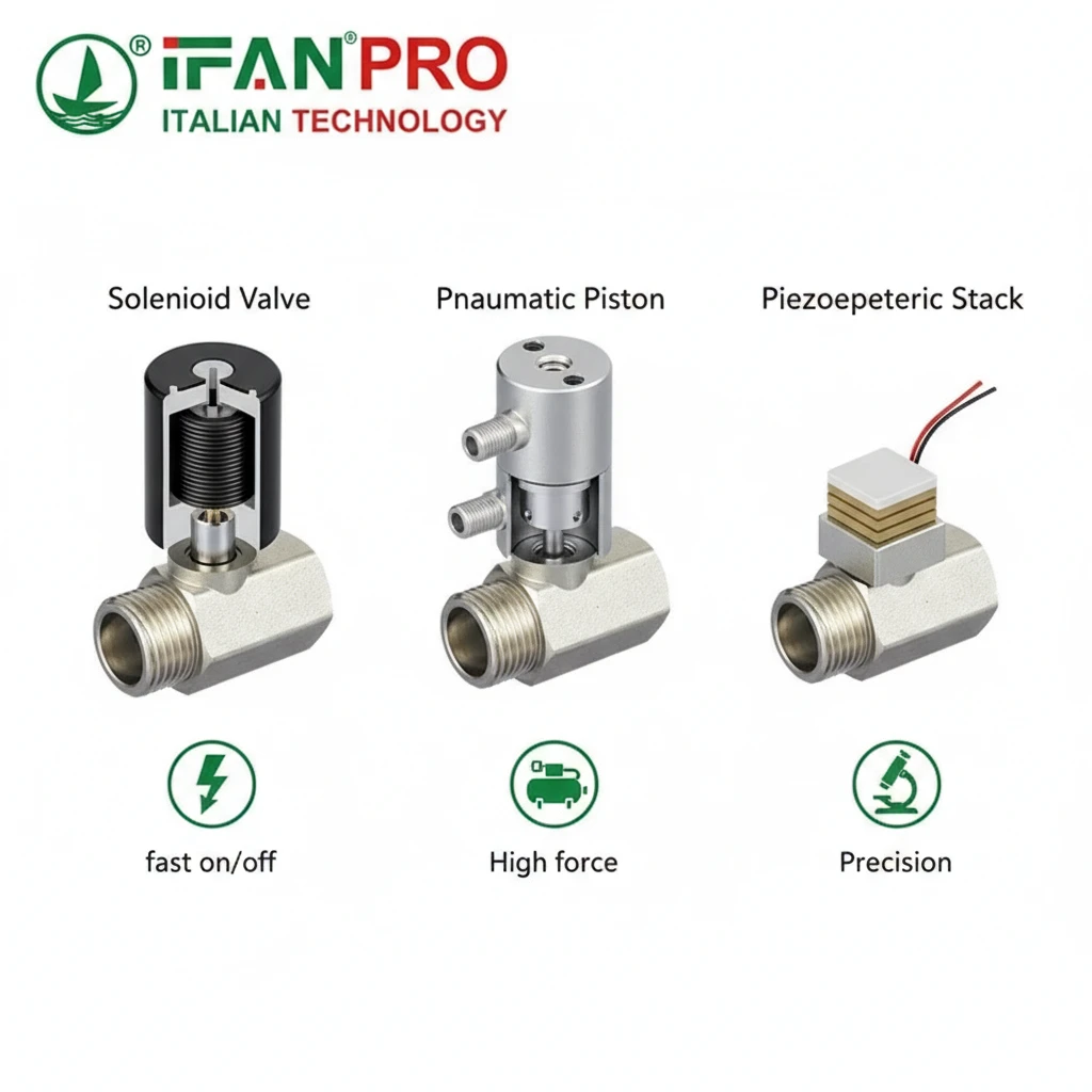
The main compatible compact actuator types for mini valves are solenoid, pneumatic, and piezoelectric actuators. Each type suits different needs. For example, people use solenoids for fast on/off electric control. They choose pneumatic actuators for high-force applications using air pressure. Engineers select piezoelectric actuators for extreme precision and miniaturization in scientific instruments.
Matching the Actuator to the Valve and Task
You must balance size, force, speed, and control method when choosing an actuator. First, note that not every small actuator works with every mini valve. The connection interface, or mounting configuration, must match. Fortunately, most manufacturers design mini valves with standard mounts for common miniature actuators.
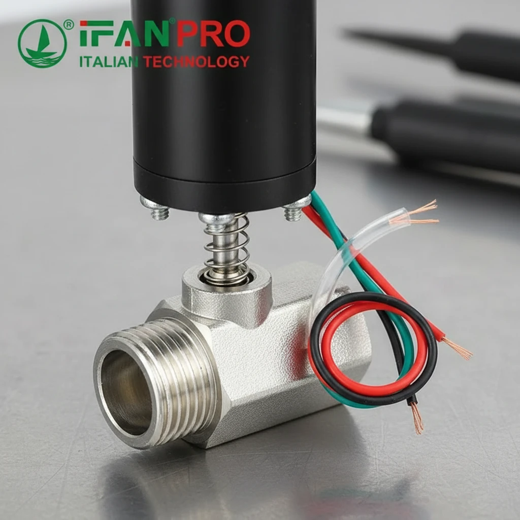
First, consider solenoid actuators. These are very common. They use an electromagnetic coil to create a pulling or pushing force on a metal plunger. This plunger connects directly to the valve stem. When you send an electric current, the plunger moves and opens or closes the valve instantly. Therefore, they are perfect for simple on/off tasks, like starting or stopping a fluid flow in an analyzer. Their main advantages are very fast response and simple electrical control.
Next, we have miniature pneumatic actuators. These use compressed air to create motion, typically moving a small piston or a diaphragm. They connect to the valve stem just like a solenoid. You apply air pressure to one side of the piston to open the valve, and to the other side (or a spring) to close it. These actuators provide more force than similarly sized solenoids. Consequently, they are ideal for environments where electricity poses a hazard. However, they require a clean, dry air supply.
Finally, piezoelectric actuators serve ultra-high-precision applications. They use special materials that change shape minutely when you apply a voltage. This allows for incredibly fine adjustments to the valve position, controlling flow with extreme accuracy. You often find them in laboratory and medical equipment. While they offer the best precision, they are generally more expensive and provide less overall force.
Actuator Comparison Guide
The table below helps you compare the core features of each actuator type.
| Actuator Type | Power Source | Best For | Key Advantage | Key Limitation |
|---|---|---|---|---|
| Solenoid | Electricity | Fast on/off switching, simple control. | Very quick response, easy to integrate with electronics. | Can generate heat, limited force for size. |
| Pneumatic | Compressed Air | Applications needing higher force or in explosive environments. | High force-to-size ratio, intrinsically safe. | Requires air compressor & tubing, slower than solenoids. |
| Piezoelectric | Electricity | Precision dosing, nano-positioning, lab equipment. | Extremely fine, precise control and positioning. | Small range of motion, high cost, complex drivers. |
In summary, compatibility depends on your valve’s mount and your application’s needs for force, speed, and precision. Always check the valve manufacturer’s specifications for recommended actuator models.
How Are Solenoid, Pneumatic, or Piezoelectric Actuators Integrated?
Integration is more than just screwing parts together. A poor link between the actuator and valve will cause failure.
Technicians integrate solenoid, pneumatic, and piezoelectric actuators with mini valves via direct mounting interfaces or linkage adapters. They mechanically couple the actuator’s moving core—like a solenoid plunger, pneumatic piston rod, or piezo stack—to the valve stem. This connection transfers motion precisely to open, close, or modulate the valve port based on the control signal.
The Mechanical Connection Process
The integration process ensures the actuator’s linear or rotary motion transfers perfectly to the valve’s closure member, like a plunger or ball. This is typically a direct, rigid connection.
For solenoid valves, integration is often the simplest. Manufacturers build many mini valves as a single, packaged unit called a “solenoid valve.” They pre-assemble the coil over the valve body. In other cases, you bolt a modular solenoid actuator, like a “box-frame” style, onto a compatible mini valve body. Here, the solenoid’s plunger aligns to push directly on the valve stem.
For pneumatic actuators, the process involves mounting a small air cylinder to the valve. The piston rod of the cylinder has a coupling that attaches to the valve stem. Then, you connect air ports on the actuator to a pilot valve, which controls the airflow. Crucially, you must ensure the actuator’s stroke length matches the valve’s required travel to fully open or close it.
For piezoelectric actuators, integration demands high precision due to their tiny movements. Engineers usually mount them via micro-adjustment fixtures. The expansion of the piezoelectric material pushes against a flexure or lever mechanism, which amplifies the motion to operate the valve stem. You often find this assembly in specialized, high-end valve blocks.
Electrical and Pneumatic Hookup
Mechanical connection is only half the job. Next, you must connect the actuator to its control system.
- For Solenoids, you need to run electrical wiring. Connect wires to the coil terminals, leading back to a driver circuit or a programmable logic controller (PLC) output card. It’s vital to use the correct voltage.
- For Pneumatic Actuators, you require air tubing. Use small plastic or metal tubes to connect the actuator’s ports to a solenoid pilot valve, which you also control electrically. This pilot valve directs the air that powers the actuator.
- For Piezoelectric Actuators, you need special high-voltage, low-current driver electronics to generate the precise voltage that controls their movement.
Always follow the manufacturer’s instructions for proper integration. Using the wrong mounting kit or misaligning the stem can cause binding, leaks, or rapid wear. A well-integrated system moves as one seamless unit.
What Control Signals and Voltages Do Automated Mini Valves Typically Use?
Clients often get confused by control signals. Using the wrong voltage can damage an expensive actuator.
Automated mini valves typically use low-voltage DC power. Common voltages include 12 VDC or 24 VDC for solenoids and piezoelectric drivers. The control signal is usually a simple on/off DC pulse for solenoids. For proportional control, technicians use a 4-20 mA analog current or a 0-10 VDC signal. Digital pulses control stepper or piezo systems.
Understanding Power Requirements (Voltage)
The voltage provides the energy to make the actuator move. Therefore, getting this right is the first step.
Most industrial solenoid coils for mini valves run on Direct Current (DC). The two most standard voltages are 12 VDC and 24 VDC. In fact, 24 VDC is especially common in factory automation because it is a safer low voltage and suffers less voltage drop over long wires. Some solenoids also come in AC voltage versions (like 120 VAC), but DC is more common for miniaturized, electronically controlled systems.
Piezoelectric actuators and their drivers often require higher DC voltages to operate, sometimes ranging from 60 VDC to 150 VDC, but they draw very little current. Pneumatic actuators themselves don’t use electrical voltage for power (they use air), but the solenoid pilot valves that control them use the same standard DC voltages (12/24 VDC).
Decoding the Control Signal
The control signal is the instruction that tells the actuator what to do. There are three main types:
- Digital On/Off Signal: This is the simplest. For example, a 24 VDC signal from a PLC output turns the solenoid ON (open). Removing the voltage (0 VDC) turns it OFF (closed), often with the help of a spring return. People use this for basic switching.
- Analog Proportional Signal: To control the position of a valve (e.g., to adjust flow rate), you need an analog signal. The most common standard is the 4-20 mA current loop. Here, 4 mA might mean the valve is fully closed, 20 mA means fully open, and any value in between sets a proportional position. 0-10 VDC is another common analog standard.
- Digital Communication Signals: For advanced networking, valves may use digital signal protocols like Pulse Width Modulation (PWM) for speed control. Alternatively, they can receive commands via Fieldbus (like PROFINET, EtherCAT) or industrial Ethernet wires. Engineers apply this more often in complex, networked systems.
Signal and Voltage Reference Table
This table summarizes the typical specifications.
| Actuator Type | Typical Power Voltage | Common Control Signal Type | Typical Use Case |
|---|---|---|---|
| Solenoid (On/Off) | 12 VDC, 24 VDC | Simple DC on/off (e.g., 24V=ON, 0V=OFF) | Quick opening/closing of fluid lines. |
| Proportional Solenoid | 12 VDC, 24 VDC | Analog (4-20 mA or 0-10 VDC) | Precisely controlling flow rate or pressure. |
| Pneumatic (via Pilot Valve) | 12 VDC, 24 VDC (for pilot) | DC on/off to control the pilot valve air direction. | Applications needing higher force. |
| Piezoelectric | 60-150 VDC (for driver) | Analog voltage (0-10V) or digital commands to driver. | Ultra-fine positioning and dosing. |
Always check the datasheet for your specific valve and actuator. You must match the control signal and voltage between your controller and the actuator for safe and reliable operation.
Can They Be Networked for Centralized Automated System Control?
Managing hundreds of valves individually is impractical. Central control is the ultimate goal of automation.
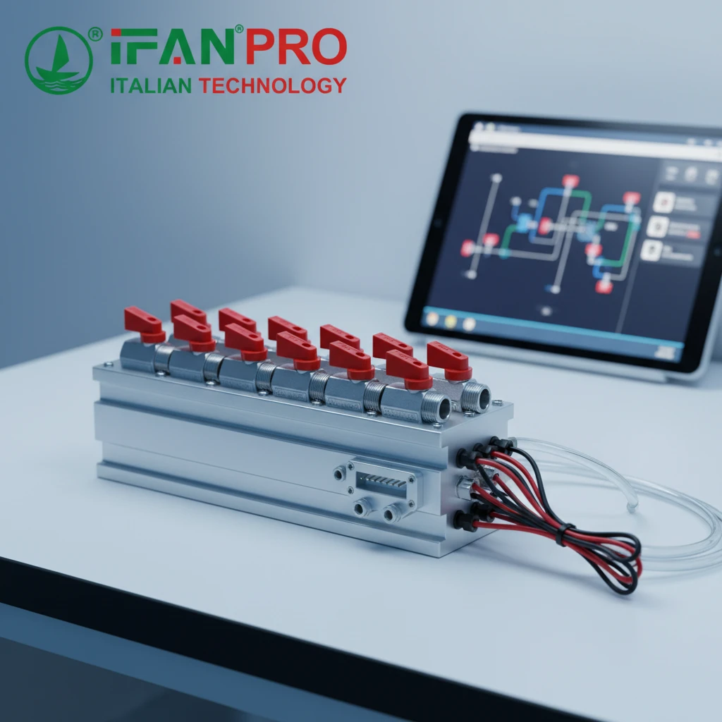
Yes, you can network automated mini valves for centralized control. Engineers connect them to a central Programmable Logic Controller (PLC) or industrial computer via digital fieldbus networks (like PROFINET, EtherCAT) or industrial Ethernet. This setup allows an operator to monitor and command all valves from a single dashboard, enabling complex, synchronized sequences.

The Architecture of a Networked Valve System
Networking transforms individual automated valves into a smart, coordinated system. Typically, the architecture has three layers.
First, at the bottom layer, are the automated valves. Each valve has its actuator (solenoid, etc.) and an electronic interface. For simple on/off valves, this might be a small I/O module (Input/Output module) that connects multiple valves. For more advanced proportional valves, each might have its own smart controller or driver board that understands digital commands.
Second, you connect these valve modules via a communication network. Instead of running hundreds of individual wires back to the control room, a single cable (often a rugged Ethernet cable) daisy-chains from one module to the next. This network uses a fast, reliable industrial protocol to transmit data.
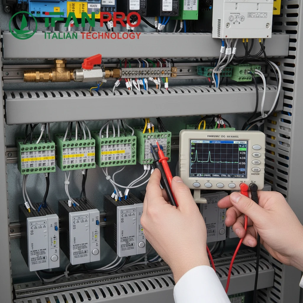
Third, at the top, is the central controller. This is usually a PLC or an industrial PC (IPC). It runs the control program that decides when each valve should open or close. It also connects to a Human-Machine Interface (HMI) – a touchscreen or computer monitor where an operator can see the status of every valve and manually override the system if needed.
Benefits of a Networked Approach
The advantages of networking are significant:
- Simplified Wiring: One network cable replaces dozens or hundreds of individual control wires. This drastically reduces installation cost and complexity.
- Centralized Monitoring and Control: An operator can see the real-time status (open/closed, fault) of every valve in the system from one screen. Furthermore, they can start complex multi-valve sequences with a single button.
- Data Logging and Diagnostics: The system can record valve operation cycles, detect failures (like a valve not moving when commanded), and predict maintenance needs. This capability helps prevent downtime.
- Flexibility and Scalability: Adding a new valve to the system often just means connecting it to the nearest network node and updating the control software.
Networking Protocol Options
People use different protocols based on speed and industry preference. Here are common ones:
| Network Protocol | Key Characteristic | Typical Application |
|---|---|---|
| PROFINET | An industrial Ethernet standard very common in European automation. | Factory automation, process control lines. |
| EtherCAT | Extremely fast and deterministic Ethernet-based system. | High-speed packaging machines, robotics. |
| Modbus TCP/IP | A simpler, older protocol that runs over standard Ethernet. | Building management, simpler industrial systems. |
| DeviceNet | A lower-cost network based on CAN bus. | Smaller machine control panels. |
In practice, for mini valve systems, engineers often group them onto a valve manifold. This manifold has the valves physically mounted on a common block, with built-in solenoids and a single network communication module. For example, IFAN offers precisely such integrated solutions, combining reliable mini valves with easy-to-network control interfaces.
Conclusion
You can effectively automate and network mini valves for precise, reliable, and centralized control. For robust, ready-to-integrate automated mini valve solutions, explore the range available from IFAN.


Commentaires récents