
I must begin with a crucial safety disclaimer: most manufacturers explicitly prohibit using PP-R pipes for compressed air systems due to significant safety risks. However, recognizing that some installations proceed despite these warnings, I’ll share essential techniques that theoretically minimize leak risks while emphasizing that proper material selection remains the safest approach.
Preventing leaks in PP-R compressed air systems requires meticulous preparation, perfect fusion techniques, adequate mechanical support, and rigorous maintenance. However, these measures cannot eliminate the fundamental safety risks associated with using PP-R for compressed air applications, and manufacturer restrictions should always take precedence over installation convenience.
Even with perfect installation, PP-R systems face inherent risks when used for compressed air. Understanding both the techniques and their limitations helps professionals make informed decisions about system safety and reliability.
What are the essential preparation steps before installing PP-R air pipes?
Proper preparation establishes the foundation for reliable system performance, though it cannot compensate for material limitations in compressed air applications.
Essential preparation includes verifying pipe and fitting compatibility, ensuring pristine cutting and deburring, maintaining ideal storage conditions, and confirming all components meet pressure rating requirements for the intended application. Meticulous preparation reduces installation variables that could compromise joint integrity in compressed air service.
Preparation begins with acknowledging the application limitations. Before proceeding with any PP-R compressed air installation, consult manufacturer specifications and local codes—most explicitly prohibit this use. If proceeding despite these restrictions, these preparation steps become critically important.
Material Selection and Verification
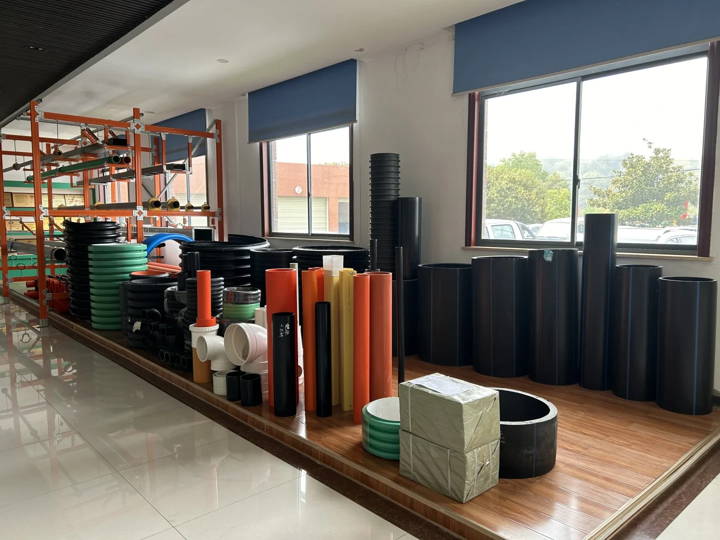
Start with selecting the appropriate PP-R classification. PN20 or PN25 grades typically offer the pressure margin needed for compressed air applications. Verify that all pipes and fittings come from the same manufacturer and production batch to ensure material compatibility during fusion. Check for certification marks and material specifications, ensuring the MRS (Minimum Required Strength) rating meets or exceeds system requirements.
Conduct a thorough visual inspection of all components before installation. Look for consistent color, smooth surfaces free from scratches or imperfections, and uniform wall thickness. Reject any materials with visible defects, as these become potential failure points under air pressure. Remember that while visual perfection doesn’t guarantee safety, visual defects almost certainly guarantee problems.
Cutting and End Preparation
Precise cutting proves crucial for leak-free fusion joints. Use dedicated PP-R cutters that produce perfectly square ends without deformation. Avoid saws that create uneven ends or generate plastic dust that can contaminate the fusion area. After cutting, use a deburring tool specifically designed for plastic pipes to remove both external and internal burrs.
Clean all components thoroughly before fusion. Wipe the pipe ends and fitting interiors with isopropyl alcohol to remove dust, oils, and other contaminants. Store prepared components in clean, sealed containers until installation to prevent contamination. Proper cleaning might seem excessive, but compressed air systems prove less forgiving of minor imperfections than water systems.
Table: PP-R Preparation Checklist for Compressed Air Applications
| Preparation Step | Critical Requirements | Consequences of Omission |
|---|---|---|
| Material Verification | Same manufacturer, batch, and grade | Incompatible fusion, joint failures |
| Visual Inspection | No scratches, consistent color and texture | Weak points, potential crack initiation |
| Precise Cutting | Square ends, no deformation | Uneven fusion, incomplete bonding |
| Deburring | Smooth internal and external edges | Turbulence, stress concentration |
| Cleaning | Alcohol wipe, no residue | Contaminated fusion, weak joints |
Consideraciones medioambientales
Control the installation environment carefully. PP-R fusion requires temperatures between 5°C and 40°C for optimal results. Cold environments make the material brittle and compromise fusion quality, while excessive heat can cause premature softening. Avoid installation in direct sunlight, as UV exposure begins degrading the material immediately.
Ensure adequate workspace organization before beginning fusion operations. Arrange all tools systematically, with the fusion welder, cutting tools, and cleaning materials readily accessible. Proper organization prevents rushed work and compromised procedures that could affect joint quality in critical compressed air applications.
How can you ensure proper fusion technique for leak-free PP-R connections?
Fusion quality directly determines joint integrity, making technique perfection essential for compressed air systems where failures carry greater consequences.
Proper fusion technique requires precise temperature control, correct heating and connection timing, adequate fusion pressure, and undisturbed cooling. The process demands calibrated equipment, trained technicians, and quality verification procedures to ensure joints achieve the required strength for compressed air containment.
The fusion process creates a molecular bond between pipe and fitting, theoretically producing the strongest part of the system. However, compressed air applications demand perfect execution, as any flaw can lead to catastrophic failure rather than gradual leakage.
Temperature and Time Control
Use only properly calibrated fusion equipment with digital temperature displays. PP-R typically requires heating temperatures between 260°C and 280°C, depending on the specific material formulation. Verify the actual heating plate temperature with an independent thermometer periodically, as inaccurate temperature readings create weak joints.
Follow manufacturer timing specifications precisely. Heating time varies with pipe diameter—typically 5 seconds for 20mm pipe up to 30 seconds for 75mm pipe. Underheating prevents proper molecular bonding, while overheating degrades the material. Use a timer rather than estimating, as even small timing deviations affect joint quality.
Connection and Cooling Process
After heating, connect the components quickly and smoothly without twisting. Apply consistent pressure to create a proper fusion bead—approximately 1-2mm for smaller diameters up to 3-4mm for larger pipes. The bead should form evenly around the entire joint circumference, indicating uniform fusion.
The cooling period proves equally critical. Support the joint to prevent movement during cooling, which typically takes 2-4 minutes depending on pipe size and ambient temperature. Never accelerate cooling with water or compressed air, as this creates internal stresses and weakens the joint. Mark completed joints with paint pens to track cooling time visually.
Table: PP-R Fusion Parameters for Different Pipe Sizes
| Pipe Diameter | Heating Time | Connection Pressure | Cooling Time | Bead Size |
|---|---|---|---|---|
| 20mm | 5 seconds | Light manual pressure | 2 minutes | 1mm |
| 32mm | 8 seconds | Moderate manual pressure | 3 minutes | 2mm |
| 50mm | 18 seconds | Significant manual pressure | 4 minutes | 3mm |
| 75mm | 30 seconds | Two-person pressure | 5 minutes | 4mm |
Quality Verification Techniques
Implement rigorous quality control for every fusion joint. Visually inspect each connection for uniform bead formation and complete circumference coverage. Any irregularity indicates improper technique and requires joint replacement. Measure the bead size with calipers to verify it falls within specifications.
Consider destructive testing for procedure qualification. Cut sample joints from each production batch and attempt to separate the components. Proper fusion should cause the pipe to tear before the joint separates. Document these tests to establish procedure validity and technician competency, particularly important for the higher risks of compressed air applications.
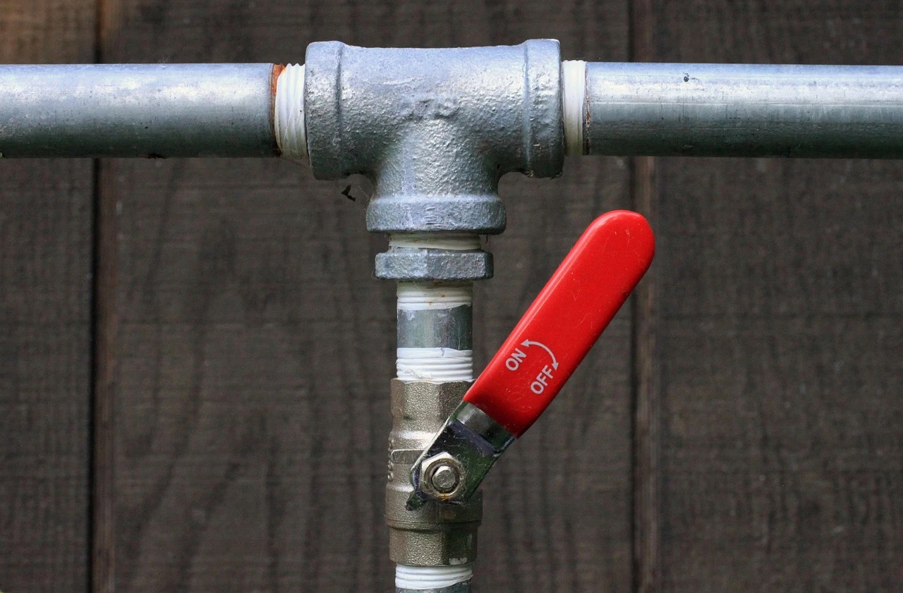
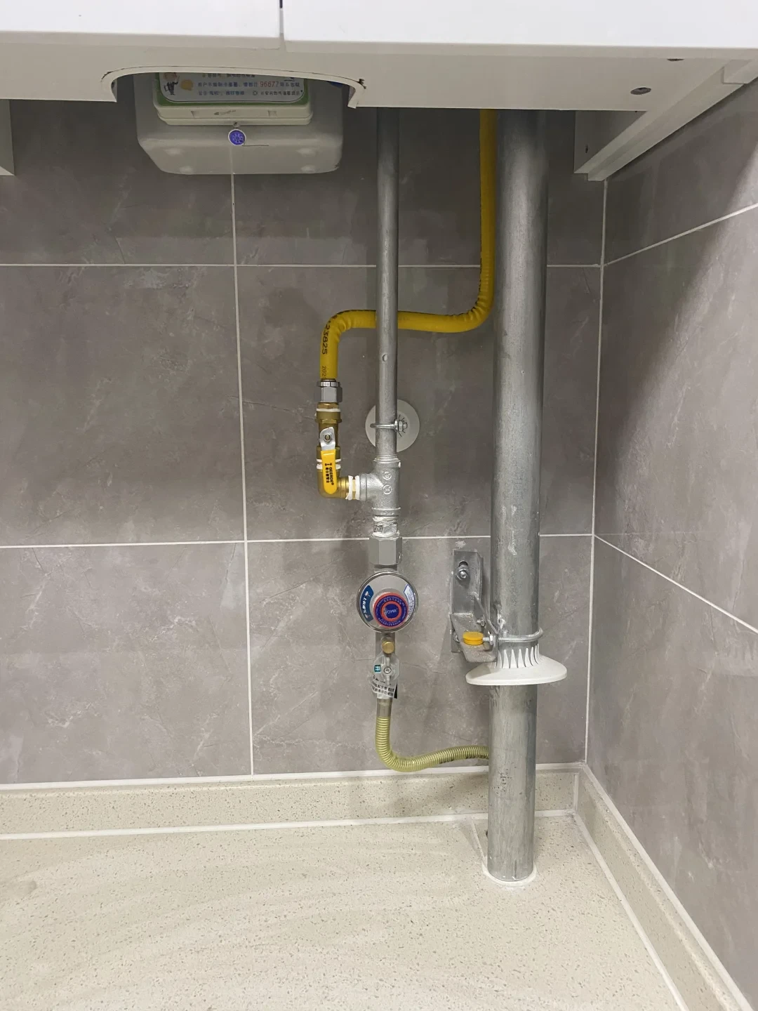
What role does proper support and clamping play in preventing pipe leaks?
Adequate mechanical support prevents stress concentrations that lead to joint failures and material fatigue, especially crucial for compressed air systems with pressure cycling.
Proper support prevents stress on fusion joints, controls thermal expansion movement, minimizes vibration transmission, and maintains system alignment. Compressed air systems require more frequent and robust support than water systems due to pressure pulsations and potential water hammer effects from quick-acting valves.
Support systems must address both static and dynamic loads in compressed air applications. Unlike water systems with relatively stable pressures, compressed air systems experience rapid pressure changes that create different mechanical stresses on the piping.
Support Spacing and Design
Follow support spacing guidelines rigorously. For horizontal PP-R pipes, supports should typically occur at 600-800mm intervals for diameters up to 32mm, increasing to 900-1100mm for larger diameters. Vertical pipes require closer spacing, typically 400-600mm for all sizes. These intervals prevent sagging that stresses fusion joints.
Select appropriate hanger materials that accommodate PP-R’s thermal expansion characteristics. Use clamps with smooth inner surfaces that don’t concentrate stress on the pipe wall. Include plastic sleeves or cushions in metallic clamps to prevent abrasion and allow slight movement during thermal expansion and contraction.
Thermal Expansion Management
Account for PP-R’s significant thermal expansion coefficient—approximately 0.15 mm/m°C. In compressed air systems, temperature fluctuations occur both from ambient conditions and from air compression/expansion. Include expansion loops, offsets, or bellows in long straight runs to absorb dimensional changes without stressing the system.
Guide pipes properly near directional changes and connections. Install guides within 300mm of tees, elbows, and valves to control movement direction. This prevents bending moments from transferring to fusion joints, which are particularly vulnerable in compressed air service where pressure cycling creates fatigue conditions.
Table: Support System Requirements for PP-R Compressed Air Pipes
| Support Type | Function | Installation Requirements |
|---|---|---|
| Standard Hangers | Vertical support | Regular spacing, cushioning material |
| Anchors | Fixed points | Strategic locations, reinforced backing |
| Guides | Control movement direction | Near direction changes and connections |
| Expansion Loops | Absorb thermal movement | Calculated dimensions, proper orientation |
Vibration and Pulsation Control
Compressed air systems generate vibrations from compressors and pressure pulsations from valve operations. Isolate the piping system from compressor vibration using flexible connectors. Install pulsation dampeners near quick-acting valves to reduce water hammer effects that can stress PP-R systems.
Consider the system’s dynamic behavior during support design. Avoid natural frequency resonances by varying support spacing slightly rather than using perfectly regular intervals. This distributed support approach prevents collective vibration amplification that could fatigue fusion joints over time in compressed air service.
How should you establish a regular maintenance schedule for air pipe systems?
Proactive maintenance identifies potential issues before they cause failures, though PP-R’s limitations in compressed air service require more vigilant monitoring than approved materials.
Establish a comprehensive maintenance schedule including visual inspections every 30 days, pressure testing every 6 months, joint examination annually, and continuous performance monitoring. Document all findings to track system degradation and identify developing issues before they cause catastrophic failures in compressed air applications.
Maintenance for PP-R compressed air systems must address both conventional piping concerns and the specific risks associated with using this material in non-recommended applications. The schedule should reflect the higher consequence of failures in compressed air systems.
Inspection Procedures and Documentation
Conduct monthly visual inspections of the entire system. Look for any signs of stress, including whitening of the material (indicating molecular orientation), deformation near supports, or scratches that could become crack initiation points. Document findings with photographs and notes, tracking any changes over time.
Perform detailed joint inspections quarterly. Examine each fusion connection for bead integrity and any signs of cracking or distortion. Pay special attention to areas near equipment connections where vibration and movement stresses concentrate. Use bright lighting and magnification if needed to identify hairline cracks that might precede failure.
Testing and Performance Monitoring
Conduct formal pressure tests every six months. Isolate sections and test at 1.5 times operating pressure for 30 minutes, monitoring for pressure drops. Document test results to identify any gradual performance degradation. Remember that while PP-R typically handles pressure well, compressed air presents different failure modes than water.
Implement continuous performance monitoring. Install pressure gauges at strategic points to identify pressure drops that might indicate developing leaks or flow restrictions. Monitor air quality for any plastic particles that might indicate internal surface degradation. Track compressor cycle frequency as increased cycling might suggest system leaks.
Table: Maintenance Schedule for PP-R Compressed Air Systems
| Maintenance Activity | Frequency | Critical Checks | Documentation Required |
|---|---|---|---|
| Visual Inspection | 30 days | Stress whitening, deformation, scratches | Photographs, condition reports |
| Pruebas de presión | 6 months | Pressure retention, joint integrity | Test pressure, duration, results |
| Joint Examination | 12 months | Bead condition, crack development | Detailed joint mapping |
| Support Inspection | 12 months | Clamp condition, alignment | Support spacing measurements |
| System Performance | Continuous | Pressure drops, air quality | Trend analysis, compressor logs |
Emergency Preparedness and System Improvement
Despite perfect maintenance, recognize that PP-R systems in compressed air service operate outside manufacturer recommendations. Develop emergency procedures for rapid system isolation and depressurization. Ensure all personnel understand the specific risks and response protocols for compressed air line failures.
Plan for eventual system replacement with approved materials. Budget for gradual migration to aluminum, copper, or steel systems specifically designed for compressed air. Document all maintenance issues to build the business case for system replacement based on operational risk rather than theoretical concerns.
Conclusión
While these techniques theoretically reduce leaks, they cannot eliminate PP-R’s fundamental safety risks in compressed air systems. Always choose materials certified for compressed air (e.g., galvanized steel, aluminum, specialized plastics). Safety outweighs any perceived installation convenience of PP-R. For help upgrading to a safe system, refer to compressed air piping standards or consult our team.


Comentarios recientes