
Most PRV mistakes start with the pipe size: a 3/4 in line gets a 3/4 in valve, and nobody checks it at peak flow. Specify a pressure reducing valve by flow instead. Name a set pressure at or below the 80 psi static ceiling in IPC 604.8 and UPC 608.2, the fall-off at your design flow, the Kv or Cv, and the minimum pressure drop and flow. Add the listing standard: ASSE 1003-23/CSA B356:23 in North America, EN 1567 in Europe.
Catalogue listings can leave out two of those: fall-off at your flow, with the pressures it was measured at, and the low-end limit below which the valve stops regulating.
Key Takeaways
- Size by flow and pressure, not pipe size: on one EN 1567 datasheet, DN32 has a kvs of 5.9 m³/h against 5.8 for DN25, and DN50 has 12.0 against 12.6 for DN40.
- IPC 604.8 and UPC 608.2 both set 80 psi (552 kPa) static as the point where a PRV is required, with limited exceptions; local amendments can change the figure.
- Set pressure has a floor too: IPC Table 604.3 asks for 45 psi flow pressure at a blowout flushometer-valve water closet and 8 psi at most fixtures.
- Where pipe is sized from UPC Table 610.4, UPC 608.2 uses 80 percent of the reduced pressure, so fall-off above 20 percent of the set pressure at design flow undercuts the pipe design.
- Ask for fall-off at your design flow with the inlet and set pressure it was measured at, plus the minimum pressure drop and minimum flow.
- A PRV for US potable water must meet the lead-free limit of a 0.25 percent weighted average on wetted surfaces.
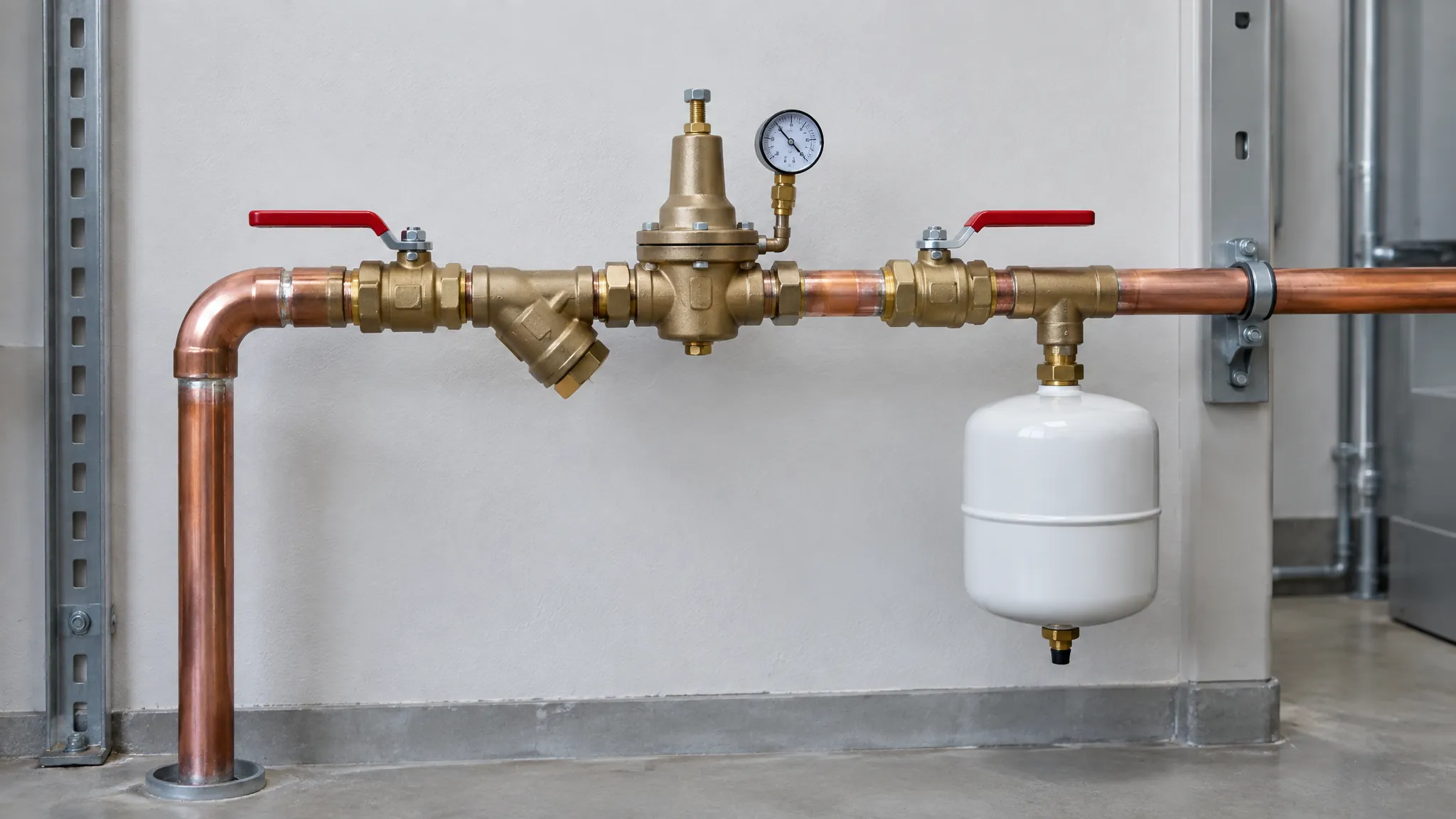
This Old House shows the installation below.

Why Pipe Size Is the Wrong Way to Pick a PRV
The connection size tells you what the valve screws onto, not what it passes. The kvs values Resideo publishes for its D06F, a valve that conforms to BS EN 1567, show the gap.
| Size (DN / in) | kvs (m³/h) | Cv (US gpm at 1 psi) | Verdict for a buyer |
|---|---|---|---|
| DN15 / 1/2 | 2.4 | 2.8 | Baseline |
| DN20 / 3/4 | 3.1 | 3.6 | 29% more than DN15 |
| DN25 / 1 | 5.8 | 6.7 | Larger size, 1.9x DN20 |
| DN32 / 1 1/4 | 5.9 | 6.8 | Same capacity as DN25 |
| DN40 / 1 1/2 | 12.6 | 14.6 | Larger size again |
| DN50 / 2 | 12.0 | 13.9 | Less capacity than DN40 |
Source: Resideo (Honeywell) D06F product specification sheet EN0H-1002GE23 R0117, kvs table. Cv converted with Cv = 1.156 × Kv, from the SI factors printed under IPC Table 604.3. Last column is our reading.
Stepping up from DN25 (5.8 m³/h) to DN32 (5.9 m³/h) on that range adds size and no capacity. Watts’ PRV product guide says the same: choose from “the flow and pressure ranges listed in the literature, not the size of the pipe”.
The opposite error is quieter: an oversized valve spends its day nearly closed, and Watts warns that oversizing can lead to wire draw under low flow.
| Connection size | kvs (m³/h) | Cv (gpm at 1 psi) |
|---|---|---|
| DN15 | 2.4 | 2.8 |
| DN20 | 3.1 | 3.6 |
| DN25 | 5.8 | 6.7 |
| DN32 | 5.9 | 6.8 |
| DN40 | 12.6 | 14.6 |
| DN50 | 12.0 | 13.9 |
Set Pressure: The 80 psi Ceiling and the Fixture That Sets the Floor
The ceiling comes from the code. Under IPC 2024 604.8, where static pressure inside a building exceeds 80 psi (552 kPa), a valve conforming to ASSE 1003 or CSA B356, with a strainer, must bring it down to 80 psi static or less (exceptions apply to sill cocks and risers). UPC 2024 608.2 draws the same 80 psi line and puts a strainer ahead of the regulator, except on regulators of 1 1/2 in (40 mm) and larger. The NYC Plumbing Code’s 604.8 uses 85 psi (586 kPa), so check the local edition.
The floor comes from the fixtures. IPC Table 604.3 lists the flow pressure each outlet needs while water runs. Most lavatories, sinks and showers need 8 psi; thermostatic or balanced-pressure shower valves and tank-type water closets need 20 psi. A urinal flush valve needs 25 psi, a siphonic flushometer-valve water closet 35 psi and a blowout one 45 psi. Take the highest of those in the building and add the height and pipe friction between valve and fixture. That is what the valve must still deliver at peak flow.
On the supply side, IPC 604.6 designs a system on a fluctuating main for the minimum pressure available. Get that minimum from the utility first; a set pressure close to it leaves the valve no room to regulate.
Fall-Off: What UPC Pipe Sizing Already Assumes
Fall-off is the drop in outlet pressure once fixtures open; the set pressure you dial in is a no-flow number. Caleffi names three drivers: inlet pressure, valve size and design, and flow rate. A fall-off figure without those conditions describes somebody else’s system.
UPC 608.2 has already spent part of it. Where pipe is sized from Table 610.4, downstream pipe is sized on 80 percent of the reduced pressure, a UPC pipe-sizing basis, not an IPC or valve requirement. The IAPMO commentary gives the reason: worst-case loss through a listed regulator is presumed to be no more than 20 percent. As a budget: a 75 psi set is sized as 60 psi (15 psi of fall-off), 60 psi as 48 psi (12 psi), 50 psi as 40 psi (10 psi).
Watts recommends its 20 psi fall-off capacity column for average installations, saying typical demand sits well within total capacity. On its 50 psi standard setting (25AUB-Z3) 20 psi is 40 percent, twice the loss UPC pipe sizing presumes, so read any capacity column against your own set pressure and flow.
A worked case shows the cost. A valve set at 60 psi that falls off 20 psi at peak flow leaves 40 psi at its outlet before pipe friction or height, below the 45 psi IPC Table 604.3 gives a blowout flushometer-valve water closet. The system passes at no flow and fails at peak demand.
The Two Numbers a Datasheet Can Leave Off
A typical listing gives connection size, maximum inlet pressure and adjustment range. Two further figures decide the fit.
Number 1: fall-off at your design flow, with its test conditions. Even a sheet that prints a flow table can leave the key off. Apollo’s 69ELF submittal lists, for the 3/4 in valve at 15 psi fall-off, 20, 27 and 32 gpm under three columns headed “Pressure Differential (psi)” and labelled A, B and C, with no psi value printed for any of them.
A note defines the differential and gives 100 psi inlet and 50 psi outlet for the flow curves, but never assigns a psi value to A, B or C. Same valve, same fall-off, a 60 percent spread in flow, and the differential behind it is not shown. Ask for fall-off in psi at your design gpm, minimum inlet pressure and set pressure.
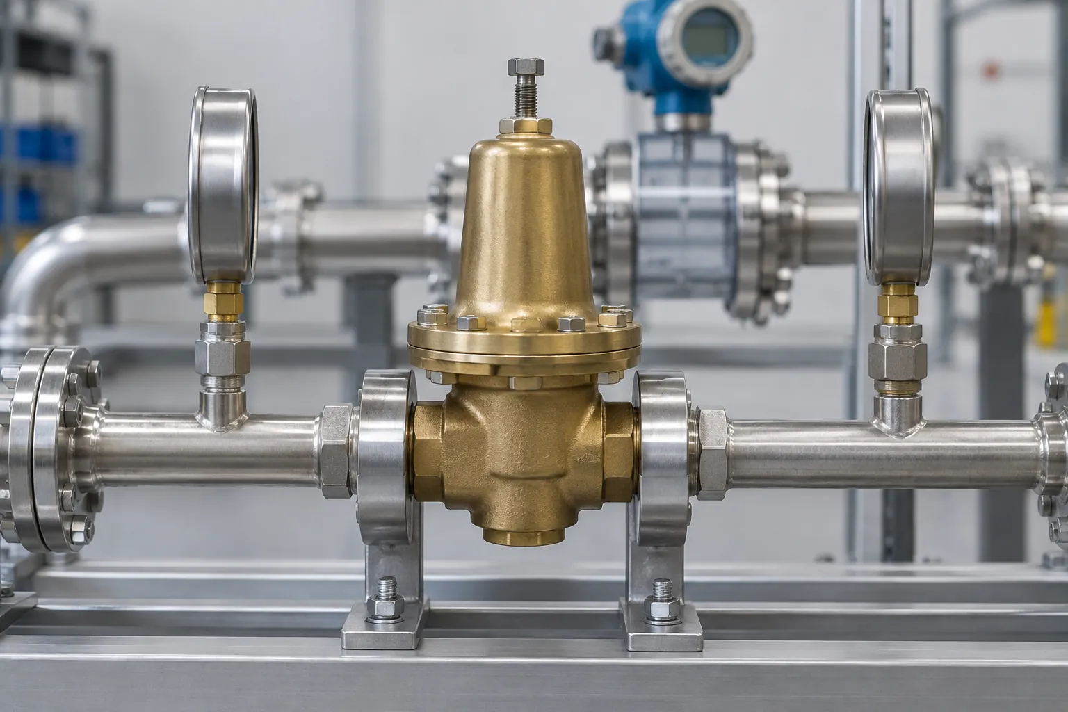
Number 2: the low-end limit. A regulating valve needs a minimum inlet-to-outlet difference. Resideo prints it for the D06F: minimum pressure drop 1 bar (14.5 psi). Below that the valve cannot hold its set pressure; the most it can pass is its kvs figure. At a 1 bar drop a fully open DN20 D06F (kvs 3.1) passes 3.1 m³/h, roughly 13.6 gpm, and no more. Minimum flow is the other half of the low end, which Watts puts at 10 to 15 percent of the system maximum.
Kv and Cv are wide-open figures, so they answer only the low-inlet case, with the drop arithmetic from our full-port vs reduced-port ball valve comparison. In normal operation only the fall-off curve describes the outlet.
Specification Checklist: What Goes on the Purchase Order
Put each line below on the RFQ. The standards lines refer to ASSE 1003-23/CSA B356:23 and BS EN 1567:1999. A supplier who fills in every line has sized the valve; one who answers with a pipe size has not.
| Item | Rule or reference | Ask the supplier for | Verdict: reject if |
|---|---|---|---|
| Standard, 1/2 to 4 in | ASSE 1003-23/CSA B356:23 (US, Canada); EN 1567, DN 8 to DN 100 | Listing or report naming model and size | Standard named without model or edition |
| Pilot-operated, over 4 in | ASSE 1103: pilot valves, 1 1/4 to 12 in | ASSE 1103 listing | ASSE 1003 claimed above 4 in |
| Set pressure and range | 80 psi static maximum (IPC 604.8, UPC 608.2) | Factory set and spring range | Your set point sits at the range end |
| Fall-off | 20% of set if pipe is sized from UPC Table 610.4 | psi at your flow, inlet and set | A figure with no conditions |
| Kv or Cv | Wide-open capacity | kvs in m³/h or Cv in gpm | Capacity given by pipe size only |
| Low-end limit | D06F example: 1 bar minimum drop | Minimum drop and minimum flow | “Not applicable” |
| Lead-free, US potable | 0.25% weighted-average lead, wetted surfaces, since 4 January 2014 | Lead-free listing (for example NSF/ANSI 372) | No listing on a US potable job |
| Failure mode | IPC 604.8.1: stays open on failure | Written confirmation of fail-open design | No answer |
| Reduction ratio | Two-stage above 4:1 or from 200 psi (Watts) | A recommendation for your inlet and set | Single stage from 200 to 50 psi |
Source: CSA Group (ASSE 1003-23/CSA B356:23 scope); Working Pressure Magazine (ASSE 1003 vs 1103); BSI Knowledge (BS EN 1567:1999 scope); IPC 2024 604.8, 604.8.1; UPC 2024 608.2 via IAPMO; 42 U.S.C. 300g-6; Resideo D06F and Watts PRV guide. Verdict column is our buying guidance.
The Station Around the Valve, and What Drives Lead Time
A PRV is never ordered alone. IPC 604.8.2 requires that valves, regulators and strainers can be repaired without breaking the pipeline or removing the valve and strainer; isolation valves either side are the usual way to service a station, though the clause does not name them. Our brass valve range covers those ball valves; IFANPRO does not list a pressure reducing valve, so the PRV itself comes from a listed maker.
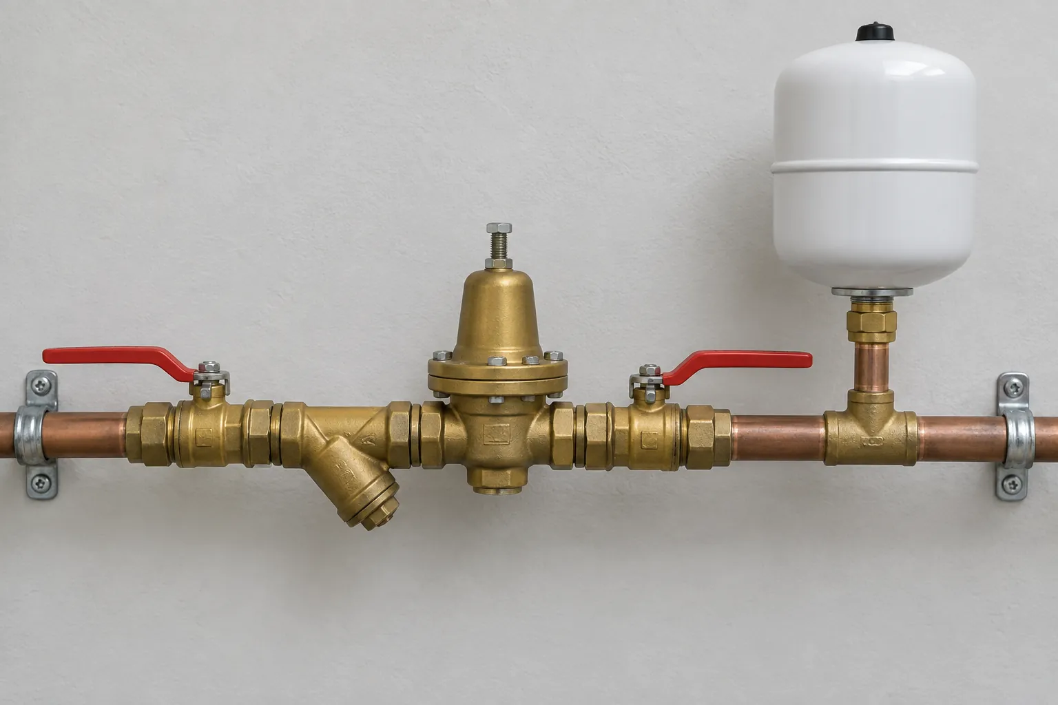
IPC 607.3 requires thermal expansion control on the cold supply of a storage water heater fed through a PRV. UPC 608.2 asks for an expansion tank downstream of each regulator, or on professionally designed systems a relief valve set at 100 psi (689 kPa) or less. For European jobs, EN 806-2, as quoted on the D06F sheet, asks for a set pressure at least 20 percent below the relief valve’s response pressure and a straight run of at least five times the valve’s nominal size after it.
Lead time depends on whether the exact model, size and spring range are already listed. A listed model ships on production time; a special spring range, factory setting or end connection may need the maker to confirm the listing still covers it, and that confirmation sets the date. Get it in writing, and check that the reduced pressure range marked on the valve, which ASSE 1003 requires, matches your PO. MOQ follows the same split: ask whether it applies per listed model or per special setting. On US potable jobs, the SDWA lead-free rules apply to the whole station, isolation valves included.
Frequently Asked Questions
What pressure should a pressure reducing valve be set to?
No code fixes one number. IPC 604.8 and UPC 608.2 set 80 psi static as the ceiling, with limited exceptions. The lower bound is the flow pressure your governing fixture needs in IPC Table 604.3, such as 45 psi for a blowout flushometer valve, plus height, friction and fall-off.
What is fall-off on a PRV?
Fall-off is the drop in outlet pressure from the no-flow set pressure once water flows. It depends on inlet pressure, valve size and design, and flow rate. Where pipe is sized from Table 610.4, UPC 608.2 uses 80 percent of the reduced pressure.
Should a 3/4 in pipe get a 3/4 in PRV?
Only if that valve carries your design flow within the fall-off you can accept. Size by flow and pressure: on one EN 1567 datasheet, DN32 has a kvs of 5.9 m³/h against 5.8 for DN25.
Does a pressure reducing valve need an expansion tank?
Often, yes. IPC 607.3 requires thermal expansion control where a storage water heater is fed through a PRV. UPC 608.2 requires an expansion tank downstream of each regulator, or a relief valve set at 100 psi or less on professionally designed systems.
What is the difference between ASSE 1003 and EN 1567?
ASSE 1003-23/CSA B356:23 covers 1/2 to 4 in pressure reducing valves for potable water in the US and Canada. EN 1567:1999 covers DN 8 to DN 100 valves in Europe, for inlet pressures up to 16 bar, 30 °C cold and 80 °C hot.
Conclusión
The risk in a PRV order is a valve that passes every static check and fails at peak flow: the gauge reads right, the connection matches the pipe, and the top floor still runs short.
Put five numbers on the RFQ: design flow in gpm, minimum inlet pressure, set pressure (80 psi static or less), allowed fall-off (20 percent of set if pipe is sized from UPC Table 610.4) and minimum pressure drop. Make the supplier answer each one.










 Español
  English
  Français
  Русский
Comentarios recientes