
We once managed a project where manual valve adjustments led to costly fluid waste. This frustrating experience cemented my belief in the power of automation for precise control.
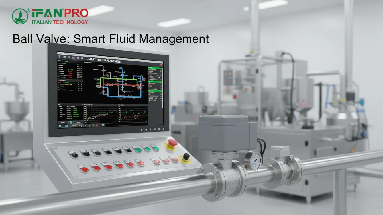
A smart ball valve optimizes fluid management automatically by integrating sensors and a controller to monitor flow conditions in real-time. It then uses pre-programmed logic to self-adjust its position, regulating flow or pressure without human intervention. This ensures consistent performance, reduces waste, and prevents system damage.
So, how does this automated magic actually work? Let’s break down the technology that turns a simple valve into an intelligent system manager.
What Sensors and Logic Enable the Valve to Self-Adjust Flow Rates?
The core pain point we see is operators guessing flow rates based on pressure gauges. Smart valves eliminate this guesswork with direct measurement.
Smart ball valves self-adjust flow rates using sensors like flow meters and pressure transducers that feed real-time data to a built-in controller. This controller applies programmed logic (like PID control loops) to compare the actual sensor reading to a desired setpoint, instantly calculating and commanding the valve’s actuator to open or close until the target flow is achieved.
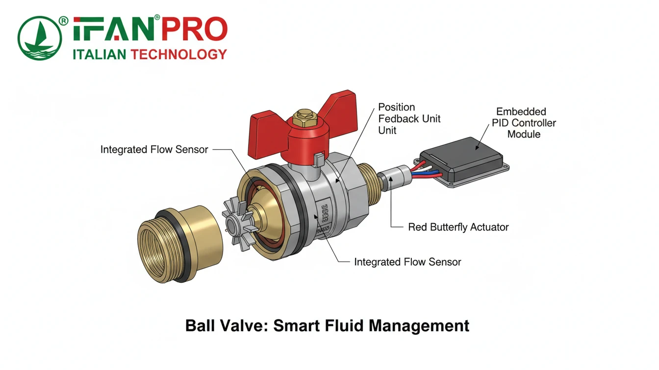
The Sensing Foundation
For any system to be automated, it first needs to “see” what is happening. This is the job of the sensors attached to or integrated with a smart ball valve. They are the eyes and ears of the operation.
The most common sensors include:
- Flow Meters: These measure the volumetric or mass flow rate of the liquid or gas passing through the pipe. They provide the direct data needed to control how much fluid is moving.
- Pressure Transducers: These measure the fluid pressure upstream, downstream, or across the valve. Pressure data is crucial for protecting the system and can also be used to infer flow.
- Position Sensors: Built into the actuator, these confirm the exact rotational angle of the ball (e.g., 45% open). This ensures the valve moves to the exact position commanded by the controller.
- Temperature Sensors: While not always used for direct flow control, monitoring temperature can be vital for process stability and safety interlocks.
The “Brain”: Controller Logic
The raw data from sensors is useless without a “brain” to interpret it. This is the controller, typically a microprocessor-based unit. Its job is to execute control logic. The most common and effective type for this task is the PID Controller.
PID stands for Proportional, Integral, Derivative. It’s a clever algorithm that doesn’t just look at the current error (the difference between the setpoint and the actual reading). Here’s a simple breakdown of how it works for a valve:
- Proportional (P): Reacts to the size of the error right now. A big error causes a big adjustment.
- Integral (I): Reacts to the history of the error. If there’s been a small error for a long time, it gradually increases the correction to eliminate it completely.
- Derivative (D): Reacts to the speed of the error change. It tries to predict what will happen next and applies a correction to prevent overshooting the setpoint.
This combination allows the valve to make smooth, accurate, and stable adjustments, quickly reaching the desired flow and holding it steady even if conditions in the pipe try to change it.
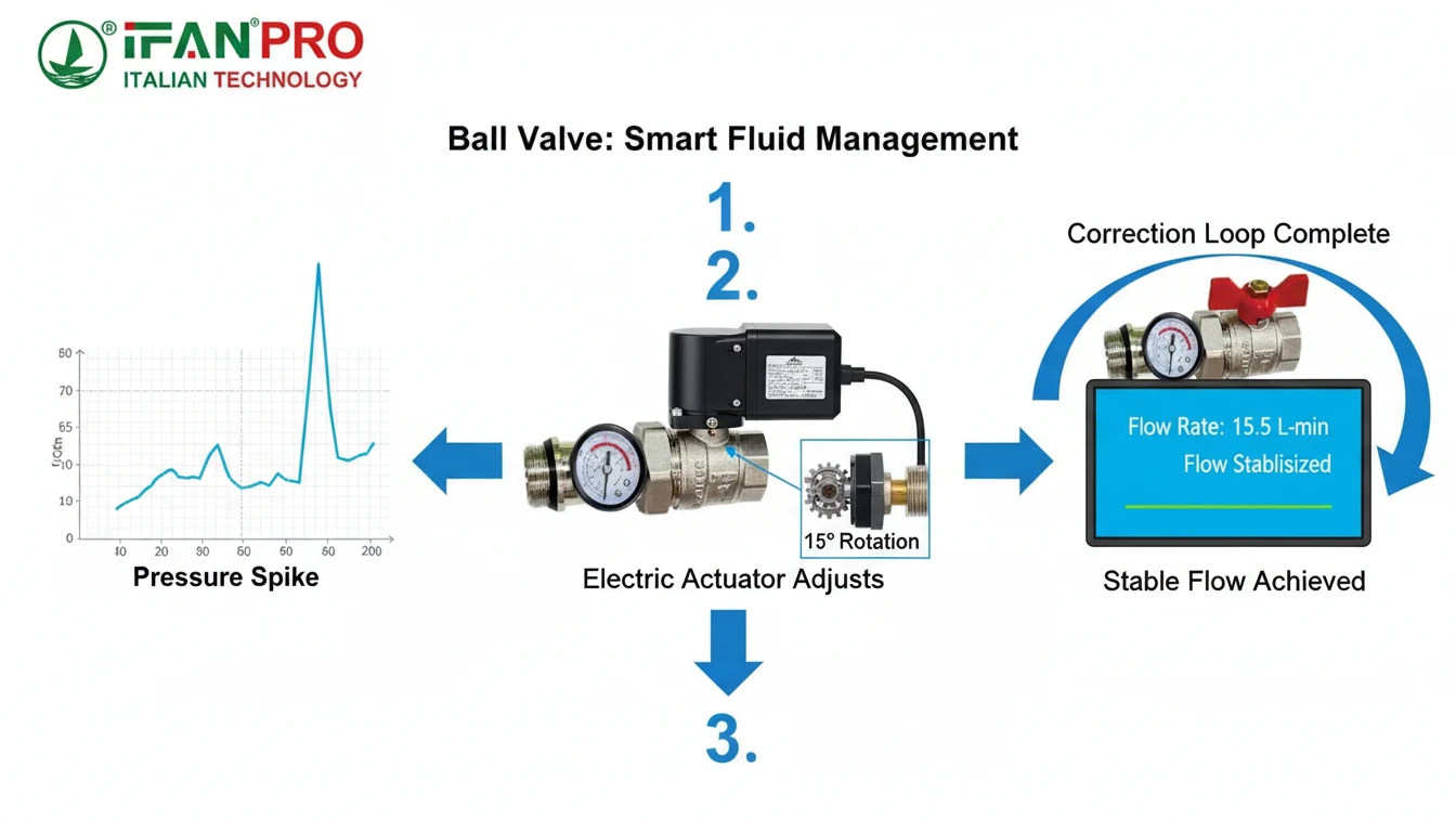
Data Flow in Automation
The table below shows the seamless process from measurement to action.
| Step | Component | Action |
|---|---|---|
| 1. Measure | Flow Meter / Pressure Sensor | Continuously sends real-time data (e.g., “Flow is 10 GPM”) to the controller. |
| 2. Compare | PID Controller | Compares the measured data (“10 GPM”) to the programmed setpoint (“15 GPM”). Calculates the error (“-5 GPM”). |
| 3. Calculate | PID Controller | Uses its P, I, and D logic to determine the exact corrective action needed (“Open valve by 15% more”). |
| 4. Actuate | Electric/Pneumatic Actuator | Receives the command and rotates the ball inside the valve to the new, precise position. |
| 5. Verify | Position Sensor | Confirms the valve moved to the correct angle, and the flow meter provides new data, closing the loop. |
This continuous “measure-compare-calculate-actuate” loop happens in milliseconds, creating a truly self-adjusting system that manual valves can never match.
How Does It Respond to Pressure Changes or Setpoint Commands Automatically?
A major client headache is system pressure spikes damaging equipment. Smart valves act as a first line of automated defense.
The valve responds automatically by treating pressure changes as a disturbance to correct and setpoint commands as a new target to achieve. Its controller continuously calculates the necessary adjustment, sending immediate signals to the actuator to reposition the valve ball, restoring stability or meeting the new command within seconds.
Responding to External Disturbances (Pressure Changes)
In real-world piping systems, pressure is never perfectly stable. A pump cycles, another valve opens or closes, or demand from equipment changes. These events cause pressure fluctuations that can affect flow and strain the system.
With a traditional manual valve, an operator might notice a pressure gauge drop hours later, by which time product quality has suffered. A smart ball valve with pressure sensing acts in real-time:
- A pressure surge occurs downstream. The sensor detects the spike instantly.
- The controller’s logic is programmed to maintain a maximum downstream pressure. It sees the new reading exceeds the limit.
- In milliseconds, it commands the actuator to close slightly. This restricts flow, increasing resistance and bringing the downstream pressure back down to a safe level.
- Conversely, if pressure drops too low, the valve can open slightly to restore it.
This automatic response protects delicate instruments, prevents pipe leaks from overpressure, and ensures consistent process conditions without anyone needing to be present.
Executing New Setpoint Commands
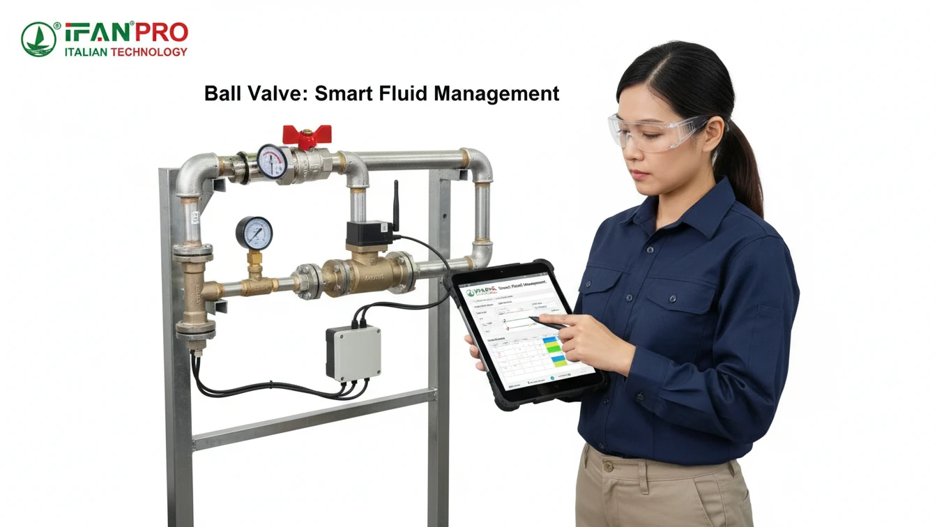
Changing a process setpoint—like increasing the flow rate for a new batch—is where smart valves show their true flexibility. This can be done via a connected software interface, a touchscreen, or a central control system (SCADA/DCS).
The process is direct:
- An operator or system sends a new command: “Change flow setpoint from 20 GPM to 30 GPM.”
- The valve’s controller receives this new target. It immediately recognizes the large difference between the current flow (20 GPM) and the new target (30 GPM).
- The PID logic calculates the fastest, most stable path to the new target without overshooting. It typically commands the actuator to open the valve quickly at first, then slow and precise as it approaches 30 GPM.
- Within a short, predictable time (often just a few seconds), the flow stabilizes at the new, precise setpoint. The entire transition is logged and can be confirmed remotely.
Speed and Reliability Comparison
This automated response is fundamentally different from manual operation. The table below highlights the key advantages.
| Scenario | Manual Valve Operation | Smart Ball Valve Response |
|---|---|---|
| Downstream Pressure Spike | Operator may notice during a round. Reacts slowly, leading to prolonged stress on the system. | Instantaneous. Corrects within seconds, minimizing risk and maintaining set conditions. |
| Command to Change Flow Rate | Operator goes to valve, uses a handwheel, checks a gauge, adjusts again—a slow, iterative, imprecise process. | Direct and Precise. New setpoint is entered digitally. Valve achieves it accurately and reports completion. |
| Response at Night/Weekends | No response until next shift, potentially leading to waste or shutdown. | 24/7 Automated Response. The system guards itself continuously, regardless of the time. |
This capability transforms the valve from a simple on/off or crude regulating device into a dynamic, responsive component of an intelligent fluid management system.
What Optimization Goals Can Be Programmed into a Smart Ball Valve?
Clients often think automation is just about convenience. We show them it’s a strategic tool for achieving specific business goals like saving money and resources.
You can program a smart ball valve with various optimization goals, including precise flow rate control, pressure regulation, energy or water conservation, batch dosing, and safety interlocks. These goals are achieved by setting specific parameters and logic rules in the valve’s controller, allowing it to make autonomous decisions that maximize efficiency and minimize waste.
Defining the Objectives
The true power of a smart valve lies in its programmability. It’s not just set to one position; it’s given a mission. Based on our work with clients in irrigation, chemical processing, and building management, here are the most common and valuable optimization goals:
1. Flow Rate Control and Modulation:
This is the most basic goal. The valve is programmed to maintain a specific, constant flow rate (e.g., 50 liters per minute) regardless of upstream pressure changes. This is essential for consistent chemical dosing, irrigation uniformity, or production process stability.
2. Pressure Regulation and Management:
The valve can be tasked with maintaining a set pressure either upstream or downstream. For example, protecting delicate filters from high pressure by regulating upstream, or ensuring a building’s upper floors have adequate water pressure by regulating downstream.
3. Conservation of Resources:
This is a direct cost-saving goal. In HVAC systems, valves can modulate coolant flow to match the real-time cooling demand, significantly reducing pump energy consumption. In water management, they can precisely control irrigation to match evapotranspiration rates, preventing water waste.
4. Batch Processing and Dosing:
For production, you can program complex sequences. A simple program could be: “Open fully for 60 seconds to fill a tank, then close completely.” A more advanced one integrates with other sensors: “Open valve at 30% flow until weight scale on tank reads 100kg, then close.”
5. Safety and System Protection (Interlocks):
These are critical “if-then” rules that override normal operation. Examples include:
- “IF the emergency stop button is pressed, THEN close the valve immediately.”
- “IF the tank level sensor reads ‘high,’ THEN close the inlet valve.”
- “IF the fire alarm is activated, THEN open the fire suppression water valve fully.”
Programming Parameters in Practice
To bring these goals to life, specific parameters are entered into the valve’s controller software. The table below shows how abstract goals translate into concrete settings.
| Optimization Goal | Typical Programmable Parameters | Practical Outcome |
|---|---|---|
| Constant Flow Rate | Target Flow Setpoint (e.g., 100 GPM), PID tuning values. | Ensures a manufacturing process receives the exact same fluid input every time, guaranteeing product consistency. |
| Energy Conservation | Differential Pressure Setpoint, Maximum Flow Limit, Schedule (e.g., reduce flow at night). | An HVAC system reduces pump speed and valve opening during off-peak hours, cutting electricity costs by 20%. |
| Precise Batching | Target Total Volume, Flow Rate during fill, Emergency shut-off conditions. | Automatically fills 50 identical mixing tanks to 500L each with perfect accuracy, freeing up an operator for other tasks. |
| System Protection | Maximum Pressure Limit, Interlock commands from other system signals. | Automatically isolates a section of pipe if a leak is detected, preventing flooding and equipment damage. |
By moving beyond simple open/close commands to these sophisticated goals, smart ball valves become key tools for achieving operational excellence, sustainability targets, and cost reduction.
How Does Automated Control Surpass Manual Valve Operation in Efficiency?
We quantify efficiency gains for clients. The shift from manual to automated control isn’t just an upgrade; it’s a transformation in reliability and cost.
Automated control surpasses manual operation by providing unmatched precision, consistent 24/7 performance, and faster response to changes. It eliminates human error, reduces labor costs for adjustments, and enables data-driven optimization of the entire fluid system, leading to significant savings in energy, water, and raw materials.
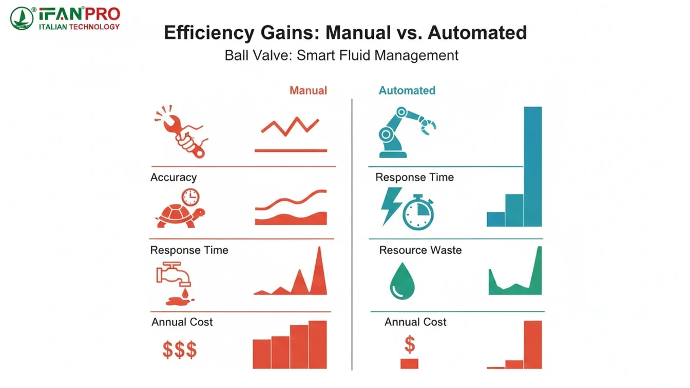
The Limitations of Manual Operation
To understand the superiority of automation, we must first acknowledge the inherent inefficiencies of manual valve control. These are the pain points we hear daily:
- Imprecision: A handwheel does not allow for precise, repeatable positioning. One operator’s “half-open” might be 40%, another’s 60%. This leads to process variability.
- Slow Response: An operator cannot monitor and adjust valves continuously. There is always a lag between a change in system conditions and the human response, leading to periods of off-spec operation.
- High Labor Cost: Sending personnel to remote or numerous valve sites for routine adjustments is expensive and time-consuming.
- No Data Logging: Manual systems offer no record of valve position or flow history, making troubleshooting and optimization guesswork.
- Reactive, Not Proactive: Manual control is inherently reactive. Something must go wrong (or be noticed) before an adjustment is made.
The Efficiency Advantages of Automation
Smart ball valves address every one of these shortcomings directly, creating a cascade of efficiency benefits.
1. Precision and Consistency:
An automated actuator can position a valve to within a fraction of a degree, repeatedly. This precise control ensures that the exact required flow is delivered every time, minimizing product quality variations and raw material waste. A chemical process no longer uses too much or too little of an expensive additive.
2. Round-the-Clock Optimization:
The system doesn’t sleep. It constantly fine-tunes itself to maintain setpoints, whether it’s 3 PM or 3 AM. This means processes run optimally on night shifts, weekends, and holidays without supervision, maximizing throughput and quality.
3. Speed and Stability:
As discussed, automated PID control responds to disturbances in seconds, not hours. This dramatically reduces the duration of “off-spec” conditions, minimizes product waste during upsets, and protects equipment from damaging pressure swings.
4. Labor and Resource Savings:
This is a major financial impact. Personnel are freed from mundane adjustment tasks for higher-value work. Furthermore, the precise control directly saves resources:
- Energy: Pumps work against precise system resistance, avoiding excess energy use.
- Water/Chemicals: Only the strictly necessary amount is used, with no over-dosing.
- Maintenance: Smooth, controlled operation reduces wear and tear on pumps, seals, and the valves themselves.
Quantifying the Difference: A Case Study Table
Let’s look at a hypothetical water treatment plant dosing scenario.
| Efficiency Metric | Manual Valve Operation | Automated Smart Ball Valve | Outcome |
|---|---|---|---|
| Dosing Accuracy | +/- 15% of target chemical flow. | +/- 2% of target chemical flow. | Smart valve saves 13% in chemical costs annually and improves treatment consistency. |
| Response to Demand Change | Operator adjusts during hourly rounds. Lag: up to 60 minutes. | System adjusts in <30 seconds. | Smart valve prevents 60 mins of off-spec water per event, ensuring constant compliance. |
| Labor for Adjustments | 2 hours per day of operator time. | 0 hours (fully automatic). | Smart valve frees up ~500 labor hours/year for other plant maintenance tasks. |
| Data for Optimization | None. | Full trend logs of flow, pressure, and valve position. | Data from smart valve identifies a 10% pump energy saving opportunity through flow analysis. |
The evidence is clear. Automated control transforms valve operation from a necessary, wasteful task into a source of competitive advantage, driving down costs and boosting reliability in a way manual methods simply cannot match.
Conclusión
Smart ball valves optimize fluid management by making intelligent, automatic decisions that ensure precision, safety, and cost savings. For advanced, reliable smart valve solutions, explore the IFAN product range to automate your system’s efficiency.


Comentarios recientes