
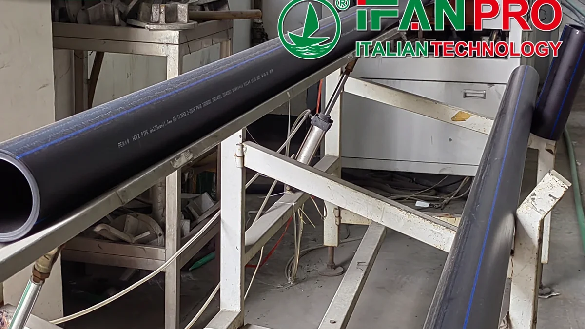
An HDPE sweep fits a preliminary route only when its centreline radius meets the governing pipe and component limit and both tangent legs plus the curved envelope fit the available space. Check geometry separately from engineering approval: a permissible radius can still put a tangent point beyond the space you have.
This is a drawing review for a simple circular sweep in an open-cut water-main route. It is not a field-bending procedure, an HDD design or permission to bend a particular product. The useful result is a dimensioned route card that distinguishes a geometry failure from a missing product or project approval.
Key Takeaways
- Use actual outside diameter and the applicable pipe and component limits; a nominal size is insufficient.
- A minimum radius controls curvature. Tangent setback controls where the curve begins and ends.
- For a simple circular sweep, tangent setback is R × tan(θ/2), and arc length is R × θ with θ in radians.
- Compare each available straight leg separately with its required setback. Spare room on one leg does not repair a shortage on the other.
- A fitting or flange inside the bend can change the radius condition; pipe-only guidance cannot qualify the assembly.
- A successful geometry screen still needs product-specific limits, the full route envelope and the project engineer’s acceptance.
This neutral circular-curve lesson explains tangent and arc lengths. It does not establish a pipe limit or approve an HDPE route.
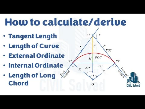
 Play: Calculating Tangent length, Long chord, External ordinate, Mid ordinate and Length of Circular Curve
CIVIL Solved · Open original video on YouTube
Radius is only the first route check
A line can look smooth on a plan and still be impossible to place between its fixed constraints. Imagine two straight centreline directions meeting at a theoretical intersection, often called PI. A circular curve replaces the sharp corner. Its tangent points sit back from PI along both lines. Those points must fall inside the space available before another fixed feature interrupts the route.
That creates two different questions. Is the curve gentle enough for the actual pipe assembly? Does that curve occupy space the route actually has? Drawing a large radius answers neither by itself. Increasing radius makes the bend gentler, but also increases the straight-leg distance it consumes at the same turn angle.
The check below treats one planar circular arc. Compound bends, changing elevation, transition curves and several closely spaced constraints need their own geometry. Do not measure a projected plan-view curve and assume it describes the full three-dimensional route.
Fix the diameter, angle and permitted radius
Record actual outside diameter, DR, pipe construction, service conditions and the written source of the allowable radius. Keep units consistent. A designation such as “110 mm” must be established as the actual OD used in the calculation, rather than assumed from a nominal label.
The Plastics Pipe Institute’s municipal field manual, 2009 edition, printed page 35, gives generic open-cut guidance by OD and DR. It also treats a fitting or flange in the bend differently. That historical guidance is a reference to discuss with the designer, not an IFANPRO product rating or evidence that a proposed assembly is approved.
Define θ as the change in travel direction between the two tangent lines. A 60° turn uses θ = 60°. Do not substitute the supplementary angle shown between extended drawing lines. Confirm which angle the drawing dimension represents before doing any arithmetic.
When the pipe series itself is uncertain, resolve that first using the IPS/DIPS tender-conflict guide. A correct equation with the wrong OD still produces the wrong route.
Turn radius into tangent setback and arc length
For a circular centreline arc tangent to both straight lines, calculate two lengths. Arc length L is the pipe centreline length around the curve. Tangent setback T is the distance from PI to either tangent point. They are not interchangeable.
| Quantity | Relationship | Drawing use |
|---|---|---|
| Angle in radians | θrad = θdegrees × π / 180 | Use this angle in arc-length calculation |
| Arc length L | R × θrad | Centreline length between tangent points |
| Tangent setback T | R × tan(θdegrees / 2) | Distance needed on each straight leg from PI |
These relationships follow from circle geometry. The arc occupies θ/(2π) of a circumference of 2πR. For setback, draw the circle centre and the two radii perpendicular to the tangent lines. The resulting right triangles give T/R = tan(θ/2). Use a calculator’s degree mode for the displayed setback equation, or convert the half-angle to radians consistently.
Compare T with each available leg, measured from the same PI. Then check the curve’s actual position against obstacles and the required installation envelope. Two adequate leg lengths alone cannot establish obstacle clearance; trench width, pipe outside surface and working space extend beyond the centreline.
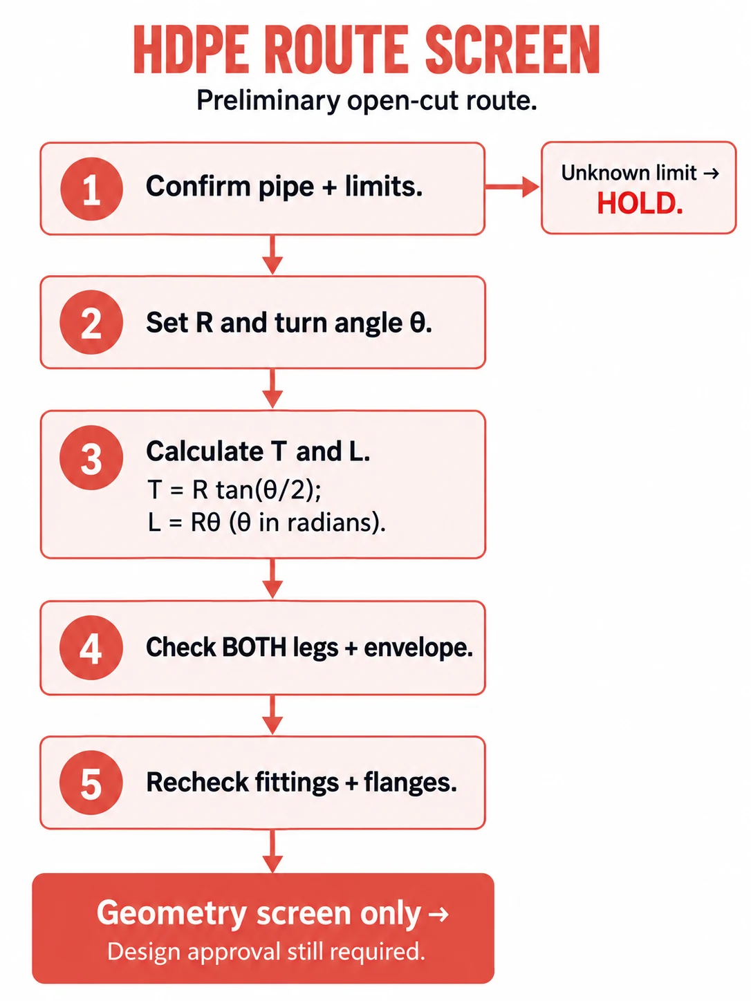
- Confirm the actual pipe and governing limits; hold the screen if a limit is unknown.
- Set the selected radius and the required turn angle.
- Calculate tangent setback and arc length with consistent units.
- Check both straight legs and the curved envelope.
- Recheck fittings and flanges, and retain the need for project design approval.
A bend that clears the radius can still miss the route
Illustrative assumptions, not a product selection or customer project: actual OD is 110 mm, DR is 11, turn angle is 60°, and a hypothetical project basis permits a 2.75 m centreline radius. One straight leg offers 1.40 m from PI; the other offers 2.00 m. The radius input is assumed accepted solely to demonstrate geometry. It does not establish approval of any pipe.
At R = 2.75 m, T = 2.75 × tan(30°) = 1.588 m. Arc length is 2.75 × π/3 = 2.880 m. The selected radius meets the assumed radius condition, but the first leg falls short by approximately 0.188 m. The second leg has sufficient length. The screen therefore fails on space, not on radius.
Trying a larger radius will not rescue that same corner: T increases with R when θ stays fixed. Reducing radius below the hypothetical accepted minimum would instead fail the radius condition. A different route position or a separately designed fitting arrangement must be evaluated.
For a changed-condition check, suppose a revised layout provides 2.00 m on both legs while retaining the same turn and radius. Both setback checks then pass, with approximately 0.412 m spare on each leg. That passes only the leg-length part of the screen. The revised curve envelope, service conditions and design acceptance remain open. Changing θ to obtain a convenient answer is not an equivalent solution when the two required directions are fixed.
A fitting inside the sweep changes the screen
A flanged connection or other rigid component is not interchangeable with a continuous pipe-only section. The PPI manual’s open-cut example uses 100 × OD where a fitting or flange is in the bend, with the larger-radius condition extending about five pipe diameters on either side of its location. Check the actual manufacturer’s component requirements as well.
In the same illustrative 110 mm OD case, 100 × OD is 11.00 m. A single constant-radius 60° arc using that radius requires T = 6.351 m and L = 11.519 m. It clearly does not fit the assumed 2.00 m legs. This is a geometry comparison using the cited generic condition, not a product-specific design decision.
Do not turn the local fitting condition into a rule that the whole pipeline must always use 100 × OD. Equally, do not keep the pipe-only curve simply because most of the arc contains no fittings. A component within the affected zone changes what must be checked. Relocating the component outside the curved section or designing different geometry requires a coordinated drawing review, including the component’s own limits.
| Quantity shown | Length (m) | Meaning in the screen |
|---|---|---|
| Initial short leg | 1.4 | Assumed initial space limit |
| Pipe-only setback | 1.588 | Required distance on each leg |
| Revised leg | 2 | Assumed revised space limit |
| Component-case setback | 6.351 | Required distance in generic-condition teaching case |
| Case | R (m) | T (m) | L (m) |
|---|---|---|---|
| Hypothetical pipe-only basis | 2.75 | 1.588 | 2.880 |
| Generic PPI component condition example | 11.00 | 6.351 | 11.519 |
Record what passed and what still needs design approval
Keep one route card with the actual OD and DR; radius source and conditions; turn angle; selected radius; calculated arc length and setback; available length on each leg; component locations; and the status of the full envelope check. Mark each result as pass, fail or unresolved. “Unresolved” is the correct result when the actual allowable radius or a component requirement is missing.
Send that card to the project designer before translating the geometry into an order. Keep open-cut geometry separate from trenchless installation design, and treat coil-versus-straight-length ordering as another decision. A delivery format does not approve a route.
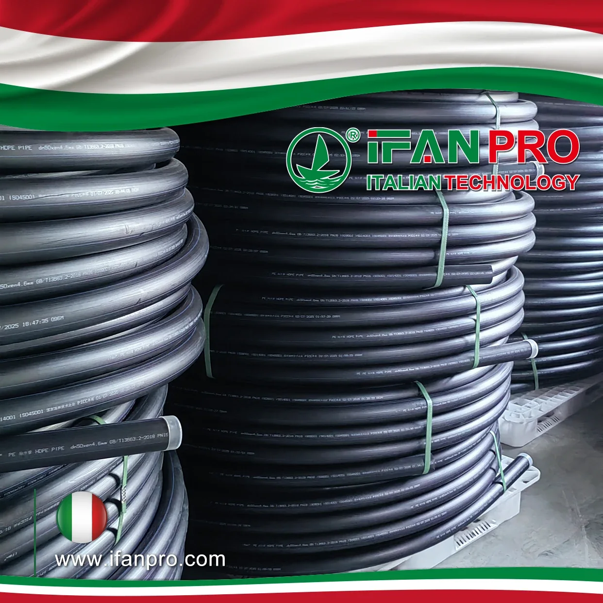
The HDPE pipe and fittings category is a starting point for product identification. No particular radius rating, matching fitting, stock, certification, MOQ or delivery time is confirmed here. After the engineer establishes the required assembly, submit the approved HDPE specification for an availability check, including country, actual OD, DR, material, duty and drawing. Ask for model-specific documentation and a confirmed delivery schedule against that identified requirement.
Conclusión
Separate the checks on the drawing: allowable curvature, tangent-leg space, curve envelope and component restrictions. Calculate the geometry against a documented radius basis, record any failure and carry unresolved inputs to the designer. A route that passes this screen is ready for the next review; it is not an instruction to bend pipe in the field.
Frequently Asked Questions
Is bend radius the same as bend diameter?
No. A circle’s diameter is twice its radius. Confirm the source and drawing use the same quantity before comparing them.
Can I use arc length as the straight-leg allowance?
No. Arc length follows the curve. Tangent setback is measured along each straight line from PI to its tangent point.
Does a coil prove that the installed curve is acceptable?
No. Supply format does not establish the allowable installed radius, component conditions or project acceptance.
Can this calculation approve an HDD bore?
No. This article screens simple open-cut route geometry. HDD involves installation and bore-design checks beyond this calculation.









 Español
  English
  Français
  Русский
Comentarios recientes