
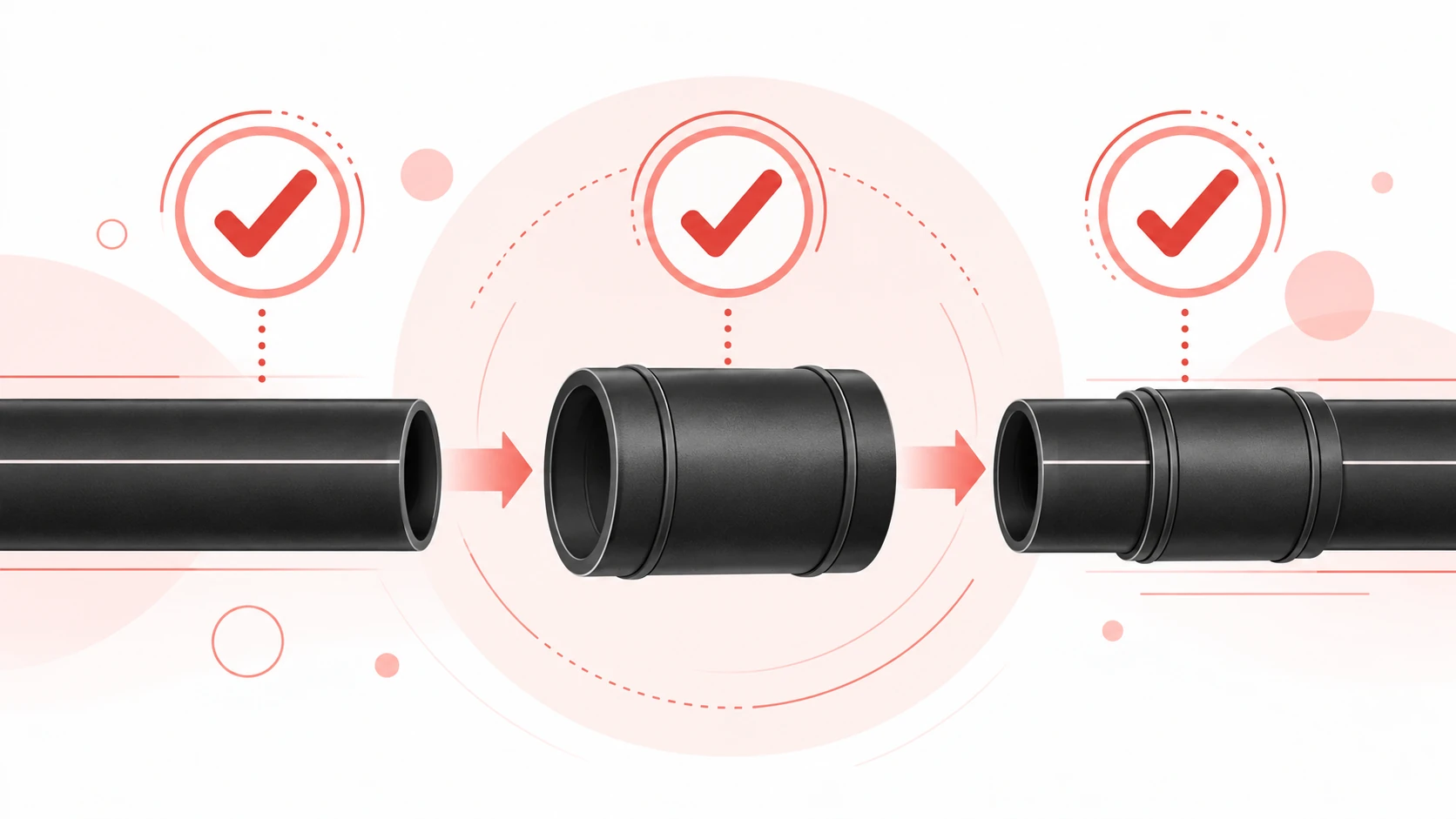
When two HDPE pipe ends are fixed, a repair connection may require an electrofusion coupler to slide completely over one end before returning across the joint. You may remove its centre stops only when the exact fitting design’s manufacturer instructions authorise that arrangement; a stop inside an unidentified coupler is not permission to modify it. The other two checks are equally important: prepare the entire pipe area contacted during travel, then locate both pipe ends in the fitting’s intended central cold zone before fusion.
These are three separate decisions. A removable stop establishes a possible assembly route. It does not establish that the pipe surface is ready or that the coupler has returned to the correct position. This guide compares named public instructions and resolves those decisions for a proposed repair; it does not supply a universal stop-removal technique or qualify an installation.
Key Takeaways
- Read permission for the exact coupling design before altering an internal stop.
- A full slide-over movement contacts more pipe surface than an ordinary insertion.
- Final pipe-end position matters independently of whether the coupler can slide.
- Named manufacturers describe different product scopes; one brand’s permission does not transfer to another.
- Without a stop, use the documented insertion and positioning method rather than estimating engagement.
- A fitting specification should identify slip-repair duty, not just say “electrofusion coupling.”
IFANGroup joining context. This video does not establish removable-stop permission or demonstrate the slip-repair configuration discussed here. Manual playback has not been verified.
Video: How to Connect HDPE Pipe with HDPE Electrofusion Fittings | Standard Step-by-Step Operation. Channel: IFANGroup. Watch on YouTube.
1. Establish permission for the exact design
An existing pipeline can prevent the axial movement used to assemble a new run. ISCO’s MTD manual separates a running joint, where the pipe can move, from a slip joint used for fixed existing pipe, including valve cut-ins and replacement sections. That distinction explains the assembly problem. It does not make every electrofusion socket a slip fitting.
The internal stop normally gives the pipe a physical insertion reference. Removing it changes that feature. Before considering removal, identify the fitting and find an explicit instruction covering that design and the proposed slide-over use. An outside photograph, a matching nominal size or another manufacturer’s repair video cannot establish the permission.
| Named source | What its instruction supports | Boundary to retain |
|---|---|---|
| Radius Systems jointing guidance, repair-coupler FAQ | Its electrofusion couplers may be adapted for repair use by removing their centre stops. | Protect the internal surface and heating element from damage and contamination. |
| ISCO MTD training manual, slip-joint section | A documented slip-assembly route for its fittings, including preparation and final positioning. | Its stop-handling method is not a generic instruction for other fittings. |
| IPEX electrofusion coupling instructions, step 7 | The document specifically notes removable centre stops for slide-over installation on couplings of 6 inches and smaller. | That note belongs to its named range; it is not a universal diameter rule. |
Sources: Radius jointing guidance, ISCO MTD installation manual, and IPEX coupling instructions. These are third-party design examples, not IFANPRO product approvals or supply partnerships.
Two apparently similar sleeves can therefore lead to different decisions. For the identified design with documented repair permission, continue to the preparation and position checks. For an unidentified stop design, select a documented slip-repair alternative or establish the exact fitting’s instruction before changing it. Do not make an ordinary coupling equivalent to a repair design by description alone.
2. Prepare the complete area the coupler will contact
Consider the movement before considering the final joint. A coupler parked fully on one pipe end passes over a longer surface than it covers on that side after it has returned across the joint. A clean-looking final overlap cannot show whether the bore and heating element crossed an unprepared area earlier.
The MTD slip-joint instruction addresses this directly. The receiving pipe, identified there as pipe A, needs preparation over the entire coupling contact length; pipe B may use the running-joint preparation described in that manual. The important relationship is the travel footprint. Do not substitute a familiar half-depth preparation mark for the longer area required by the actual assembly movement.
| Check | Area or position to establish | Incorrect shortcut |
|---|---|---|
| Parking the sleeve | The full pipe area contacted while the coupling travels onto one side. | Preparing only its final overlap. |
| Returning across the joint | The documented final engagement of both pipe ends. | Assuming a freely sliding sleeve is centred. |
| Ready for the cycle | Prepared surfaces and the specified supported, restrained assembly. | Assuming removable-stop permission approves the completed joint. |
This also changes how you assess a partly prepared repair. If the sleeve must move beyond the prepared surface, the proposed assembly is not ready. Correct the preparation footprint using the applicable pipe, fitting and tool instructions before sliding it into place. The correction is extra length of properly prepared surface, not an invented extra scraping depth.
Radius’s warning about protecting the bore and heating element remains relevant during adaptation and handling. The pipe surface is only one side of the interface. A damaged or contaminated fitting interior does not become acceptable because the pipe underneath was prepared correctly.
3. Return both pipe ends to the intended central cold zone
Once a coupling can slide freely, there is a new risk: it can travel too far or not far enough. Without the stop, a smooth fit is no longer a physical confirmation of final insertion depth. External reference marks and the manufacturer’s positioning instructions must establish where the pipe ends finish.
The MTD manual identifies the required result for its slip joint: the pipe ends terminate within the central cold zone rather than ending short inside a fusion zone. Its failure examples distinguish a correctly located joint from one with one end too deep and the other too shallow. That is why “the sleeve covers the gap” is an incomplete acceptance statement.
There is no universal gap allowance on this page. Coupling geometry and the applicable instructions determine the permitted arrangement. Do not copy an allowance from a different diameter or treat an approximate central position as a substitute for the fitting’s specified insertion method.
- Identify the design: establish whether its instructions authorise the stop removal or slip configuration.
- Map the movement: identify the entire pipe surface contacted as the sleeve is parked and returned.
- Apply the specified preparation: complete that footprint and protect the fitting interior.
- Locate the joint: use the documented marks and insertion method to place the ends in the intended cold-zone position.
- Retain the assembly: use the applicable support, restraint, fusion and cooling instructions; sliding permission changes none of those obligations.
This is a selection and verification sequence, not a substitute welding procedure. The exact product’s instructions still control the physical removal method, tooling, preparation dimensions and cycle. For broader joining-method choices, use the HDPE fusion overview.
Three completed repair decisions
The following are illustrative configurations, not IFANPRO installations or supplied-product examples. Each changes one controlling condition so the answer changes for a stated reason.
A documented removable-stop design, with the full path prepared
A proposed repair uses an identified coupling whose current instructions authorise slide-over installation. Its compatible pipe and service have already been checked, the entire travel contact area is prepared as required, and the final position can be established using that instruction’s reference method.
Decision: slip assembly is a documented option for this configuration. Follow that named procedure through positioning, restraint, fusion and cooling. The result follows from the identified design and completed checks, not from a general claim that every electrofusion fitting can be converted.
An unidentified stop design on an otherwise matching sleeve
The available coupling fits the stated pipe diameter, but there is no identified instruction permitting its internal stop to be removed. A photograph of a different brand shows a removable tab.
Decision: the photograph does not authorise modification. Choose a documented stopless or removable-stop repair design that matches the pipe and service, or resolve the exact product identity and instruction before accepting the existing sleeve for this job. A matching diameter answers fit; it does not answer design permission.
A suitable design, but only ordinary insertion length prepared
The coupling is documented for slip repair, yet the prepared pipe area ends before the point the sleeve must reach when parked fully on one side.
Decision: correct the preparation footprint before assembly. Permission is present; the travel-contact condition is not. After preparation, re-establish the final reference marks and positioning check. Merely returning the sleeve to a clean final area would leave its earlier contact with the unprepared area unexplained.
Specify the coupling’s actual job
A useful fitting enquiry describes two fixed pipe ends and the proposed slide-over movement. Include the pipe identification, actual outside diameter, SDR or wall information, service conditions and destination requirements. Ask which exact coupling design is proposed, whether it is stopless or has an authorised removable stop, and which current assembly instruction covers the repair.
That produces a checkable specification instead of an ambiguous “repair coupling” line. It also keeps this task separate from deciding whether a mechanical band can provide a permanent local seal; that different question is covered in the HDPE repair-clamp guide.
IFANPRO publishes an HDPE pipe and fittings category. Availability and documentation for a particular slip-repair design have not been confirmed here. No Radius, IPEX or MTD stock, interchangeable approval or IFANPRO removable-stop SKU is claimed.
Submit your pipe and coupling requirements for an availability check, including the fixed-end repair duty and required design documentation.
Conclusión
Start with the exact design’s permission, map the full travel contact area, then establish the final pipe-end position using its documented method. A removable stop can make a slip repair possible; correct preparation and cold-zone positioning make that permission usable. Keep all three decisions together when selecting the coupling.
PREGUNTAS FRECUENTES
Can I remove a centre stop from any electrofusion coupling?
No. Use the exact design’s manufacturer instruction. Permission for a named Radius, IPEX or MTD fitting does not authorise alteration of an unidentified coupling.
Is preparing half the coupling length always enough?
No. A slip arrangement can require the sleeve to pass fully over one pipe end. Prepare the complete contact area required by that movement and the applicable instruction.
Does a freely sliding coupling prove correct engagement?
No. The final pipe-end position must be established independently. The MTD slip procedure places the ends within the central cold zone, not short inside a fusion zone.
Does IPEX’s 6-inch note set a universal slip-coupling limit?
No. It describes the named range in that instruction. Other designs need their own documented permission and installation requirements.
Written by Justin, IFANPRO editorial team. Based on public manufacturer instructions; no firsthand repair, field test or particular coupling supply is claimed.











 Español
 English
 Français
 Русский
Comentarios recientes