
I remember the first time I was responsible for a hydrostatic test. The pressure gauge was climbing, and my heart was racing. A single mistake could mean a costly, dangerous failure.
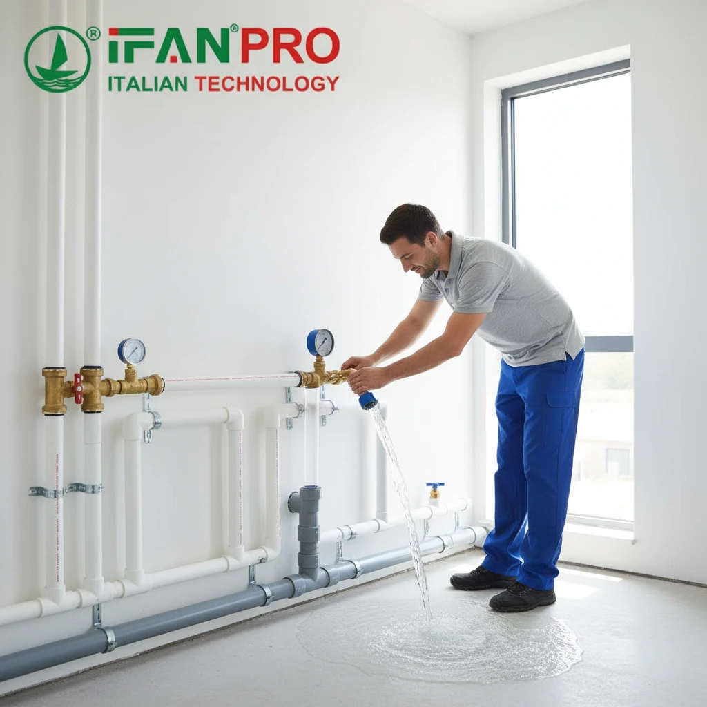
To perform a hydrostatic pressure test, you fill the piping system with water, pressurize it to 1.5 times its design pressure, hold it for a specified time, and inspect for leaks or pressure drops. It’s the definitive method to prove a new system’s structural integrity and leak-tightness before it goes into service.
While the core concept is simple, the devil is in the details. A poorly executed test is useless at best and catastrophic at worst. This guide will walk you through the entire process, from understanding the ‘why’ to mastering the ‘how,’ ensuring your next test is safe, compliant, and conclusive.
What is the purpose of a hydrostatic pressure test?
Why go through the hassle of filling a system with water and pumping up the pressure? I used to think it was just a box to check, until I saw a small weld crack under pressure that no visual inspection could have found.
The primary purpose of a hydrostatic pressure test is to verify the structural integrity and leak-tightness of a pressure-containing system, like a pipeline or vessel. It subjects the system to stresses above its normal operating conditions to ensure it can safely perform its intended function.
Beyond Just Finding Leaks: The Three Core Objectives
Most people think a hydro test is just about finding leaks. That’s a critical part, but it’s only one of three main objectives. The test serves as a comprehensive physical examination of your entire piping system.
First, it tests for strength. By pressurizing the system to 150% of its design pressure, we are essentially giving it a “stress test.” This reveals any weaknesses in the materials, such as substandard pipe, or in the construction, like a faulty weld. A component that holds at 150% pressure will have a significant safety margin for its normal 100% operating life.
Second, it tests for leak-tightness. This is the most visible objective. We look for any weeping or dripping at flanges, threaded connections, valve stems, and welds. Even a tiny leak under high-pressure water will be evident, whereas a small gas leak might go undetected.
Third, it serves as a final verification of the design and installation. The test confirms that all components—pumps, valves, gauges, supports—are correctly installed and function as an integrated system under pressure. I’ve seen tests fail because a support was missing, causing excessive sag and stress on a pipe section.
Regulatory and Safety Drivers
You don’t just do this test because it’s a good idea; you often do it because you have to. Compliance is a major driver.
In the United States, the American Society of Mechanical Engineers (ASME) Boiler and Pressure Vessel Code (BPVC) and the American Petroleum Institute (API) standards provide the rules. For pipelines, the Department of Transportation (DOT) through the Pipeline and Hazardous Materials Safety Administration (PHMSA) has strict mandates. These codes specify everything from test pressure and duration to water quality and safety procedures.
From a safety perspective, the test is non-negotiable. The energy stored in a pressurized system is immense. A rupture can cause catastrophic damage, injury, or loss of life. Testing with water is safer than testing with air or gas because water is nearly incompressible. If a failure occurs, the water releases very little explosive energy compared to a compressed gas.
| Testing Objective | What It Checks For | Why It Matters |
|---|---|---|
| Structural Strength | Material flaws, weak welds, inadequate wall thickness. | Prevents catastrophic rupture during operation. |
| Leak-Tightness | Leaks at flanges, threads, valves, fittings. | Ensures system efficiency and prevents environmental/safety hazards. |
| System Verification | Proper installation of all components and supports. | Confirms the built system matches the design intent. |
| Cumplimiento de la normativa | Adherence to ASME, API, DOT, and local codes. | Legal requirement for operation and insurance. |
What safety precautions are essential before starting the test?
I once saw a test blind that wasn’t properly secured become a high-pressure projectile. It embedded itself in a wooden fence like a spear. That moment burned the importance of safety prep into my mind forever.
Essential safety precautions include creating a formal test plan, establishing a clearly marked exclusion zone, verifying all isolation blinds and valves, ensuring pressure relief devices are functional, and using personal protective equipment (PPE). Never underestimate the stored energy in a pressurized system.
The Foundation: A Written Test Plan and Permit
You should never start a hydro test without a written plan. This document is your playbook. It should detail the test scope, pressure limits, hold time, equipment to be used, and a step-by-step procedure. Crucially, it must include a Job Safety Analysis (JSA) or similar hazard assessment. This process forces the team to think through every potential risk—from falling objects to slips on wet surfaces—and define mitigation measures.
This plan is the basis for a work permit, typically a Pressure Test Permit. The permit system ensures that all pre-conditions are checked and signed off by authorized personnel (operations, maintenance, safety) before any pressure is introduced. It’s a critical administrative control.
Physical Safeguards and Zone Control
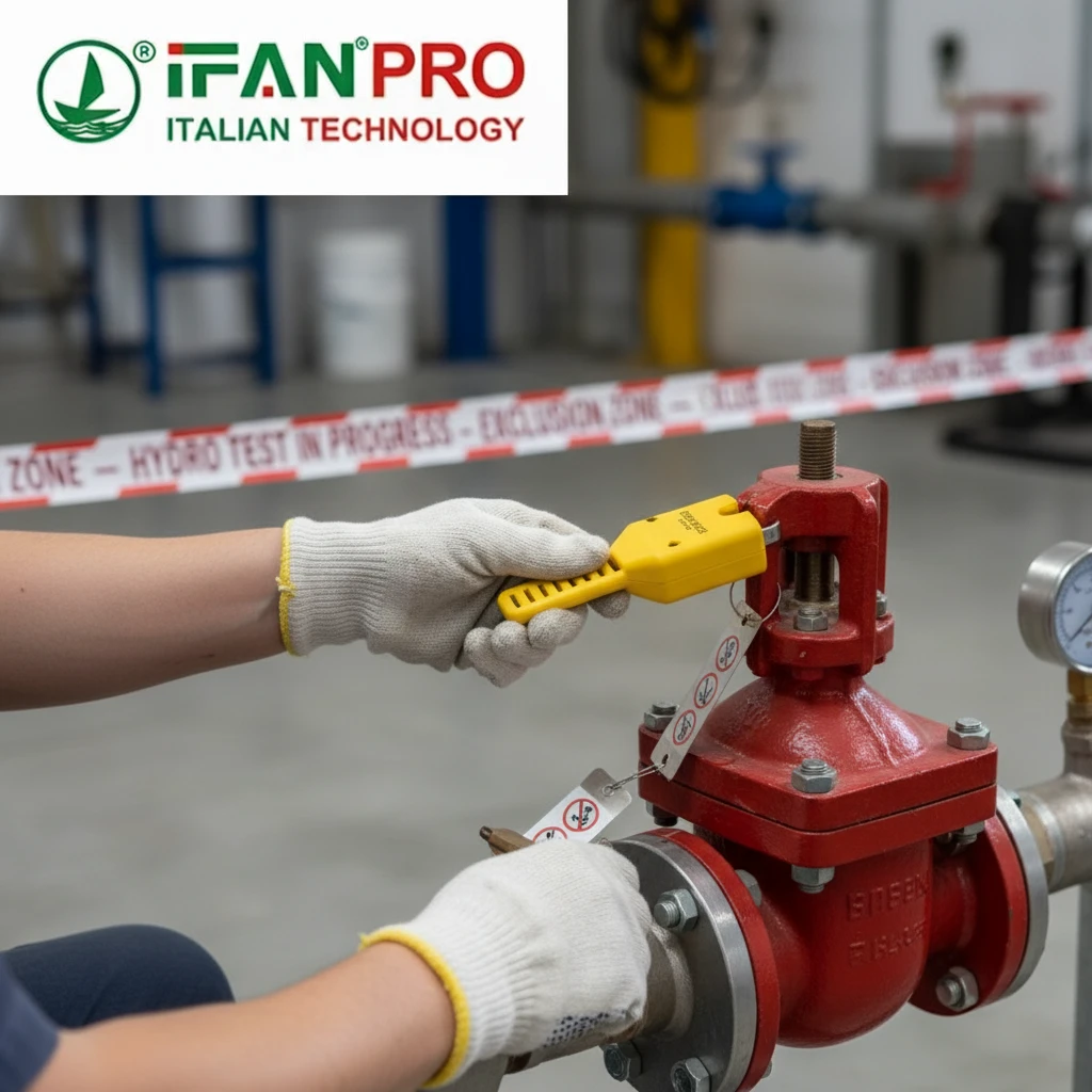
Once the paperwork is in order, you establish physical control. The most important step is setting up an exclusion zone. This is an area around the test section where no unauthorized personnel are allowed during pressurization and hold. It should be marked with barriers, danger tape, and signs stating “HYDRO TEST IN PROGRESS – KEEP OUT.”
Inside this zone, you must verify all isolation points. This means checking that blinds (solid plates) are installed correctly and tagged, and that valves isolating the test section are locked or tagged in the correct position. Connecting to an active system by mistake is a common and dangerous error.
You must also install a properly sized and calibrated relief valve on the test system. This valve is your last line of defense against over-pressurization. It should be set to open at or just above the required test pressure.
Personal Preparedness and Equipment Checks
The human element is key. All personnel involved must be briefed on the test plan, emergency procedures, and communication signals. Everyone must wear appropriate PPE: safety glasses, steel-toe boots, and often face shields and hearing protection near pumps.
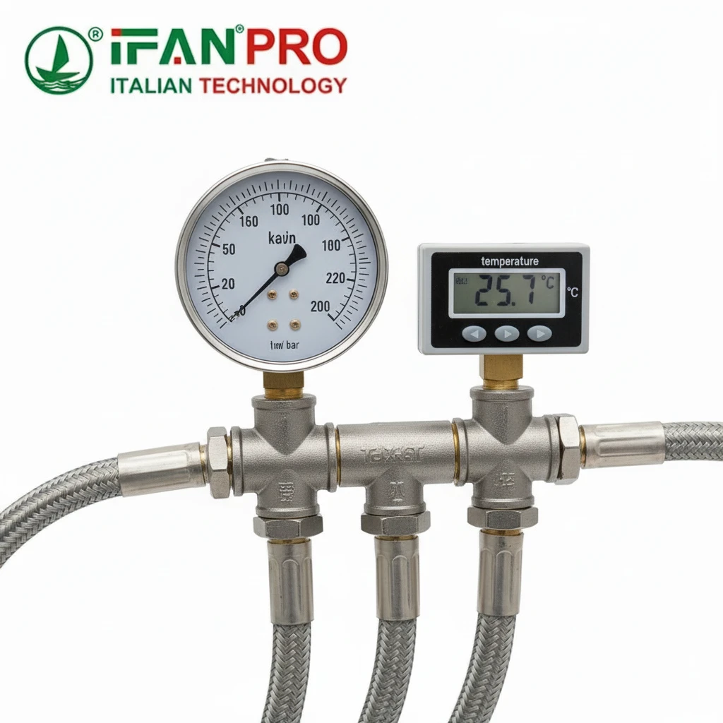
Equipment checks are non-negotiable. All pressure gauges must be recently calibrated and have a range such that the test pressure falls in the middle third of the scale (e.g., use a 0-3000 psi gauge for a 1500 psi test). Hoses and fittings must be rated for the test pressure and in good condition. The pump must be equipped with a dead-man switch or similar control.
| Safety Category | Key Precautions | Tool/Control Method |
|---|---|---|
| Administrative | Written Test Plan, Job Safety Analysis (JSA), Work Permit. | Paperwork, sign-off sheets, permit-to-work system. |
| Physical / Zone | Establish Exclusion Zone, Verify Isolation (Blinds/Valves), Install Relief Valve. | Barriers, tags/locks, calibrated relief valve. |
| Personal & Equipment | Personnel Briefing, Proper PPE, Calibrated Gauges, Rated Hoses/Fittings. | Safety meeting, PPE gear, calibration certificates, equipment inspection. |
What is the step-by-step procedure for conducting the test?
Following a strict procedure turns a potentially chaotic operation into a controlled, repeatable process. Skipping steps is how tests fail—or worse, cause accidents.
The step-by-step procedure involves: 1) Preparation and isolation, 2) Filling and venting, 3) Pressurization to test level, 4) Holding and visual inspection, and 5) Depressurization and drainage. Each phase must be controlled and documented.
Phase 1: Preparation and Isolation (The “Lockout”)
This is the most critical phase for safety. First, ensure the test plan is approved and all personnel are briefed. Then, physically isolate the test section from all other piping and equipment. Install spectacle blinds or spade blinds at all connection points. These are unambiguous physical barriers. If using valves for isolation, they must be locked and tagged in the closed position. Install the pressure gauges (at least two, preferably at high and low points) and the relief valve. Connect your fill line and pump to the designated low-point connection.
Phase 2: Filling and Venting (Getting the Air Out)
Begin filling the system slowly with water. The water should be clean; muddy water can clog instruments or hide small leaks. As the system fills, you must vent all high-point vents. Air trapped in the system is dangerous because it compresses, storing significant energy. It also makes pressure readings unstable. Keep venting until a steady stream of water, not air, comes out of every vent. This can take a surprisingly long time on a large, complex system. Once full, walk the entire line again, tapping to check for hollow sounds that indicate trapped air.
Phase 3: Pressurization (The Controlled Ramp-Up)
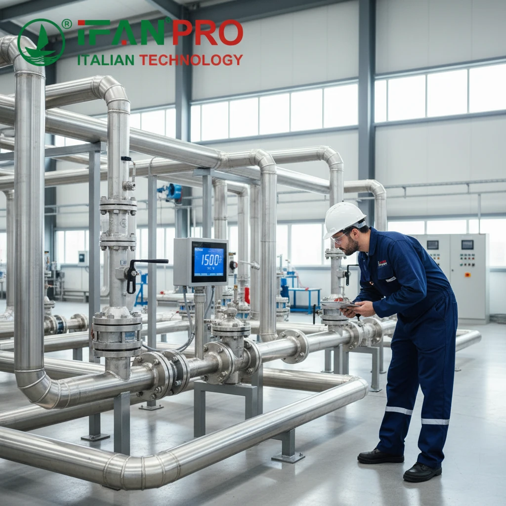
With the system full and vented, start the pump. Increase the pressure slowly and steadily. A good rule is to raise pressure in increments of no more than 10% of the test pressure, pausing for a few minutes at each step. This allows the system to stabilize and gives you a chance to perform a preliminary visual inspection for major leaks. Monitor all gauges continuously. The pressure should rise smoothly. Once you reach the required test pressure (typically 1.5 x design pressure), immediately stop the pump and close the isolation valve between the pump and the test section.
Phase 4: The Hold and Inspection (The Proof)
This is the test’s core. Once isolated, the clock starts on the hold time, usually a minimum of 1-2 hours as per code, but often longer for large systems. The pressure will likely drop slightly initially due to temperature changes or minor expansion, then stabilize. Your job is to continuously patrol the exclusion zone, performing a meticulous visual inspection. Look for drips, weeping, bulging pipes, or movement in supports. Record the pressure at the start and end of the hold period. A stable pressure with no visible leaks is a pass.
Phase 5: Depressurization and Drainage (Safe Return to Zero)
Do not just open a valve and blow the water out. Depressurize slowly and controllably through a designated drain valve. A sudden release can cause water hammer, damaging the system. Once pressure is near zero, open all vents to break any vacuum as you drain. Drain the water to an appropriate location, considering any environmental regulations. Finally, remove the test blinds, reconnect the system, and update all documentation with the test results.
| Procedure Phase | Key Actions | Success Criteria / What to Watch For |
|---|---|---|
| 1. Preparation & Isolation | Install blinds, lockout valves, install gauges/relief valve, connect pump. | Test section is 100% isolated. All equipment is rated and ready. |
| 2. Filling & Venting | Fill with clean water, vent all high points until water flows steadily. | No air bubbles at vents. System sounds solid when tapped. |
| 3. Pressurization | Increase pressure in 10% increments. Stop at required test pressure. | Smooth pressure rise. No major leaks during ramp-up. |
| 4. Hold & Inspection | Isolate system, start timer. Visually inspect entire length for leaks. | Pressure stabilizes. No visible weeping, dripping, or movement. |
| 5. Depressurization & Drainage | Slowly release pressure via drain valve. Open vents, drain system. | Controlled pressure drop to zero. Safe disposal of test water. |
How do you interpret the test results and identify failures?
Seeing the pressure hold steady is a great feeling, but you need to know what the numbers and your eyes are really telling you. A “pass” isn’t just the absence of a giant leak.
You interpret test results by comparing the starting and ending hold pressures, accounting for temperature changes, and conducting a thorough visual inspection. A failure is indicated by a pressure drop exceeding allowable limits or any visible leakage, weeping, or permanent deformation of components.
Understanding Pressure Behavior: It’s Not Always a Leak
The pressure gauge is your primary instrument, but you must read it intelligently. A small pressure drop during the hold period does not automatically mean failure. The most common cause of a pressure drop is a change in water temperature. If the water cools, it contracts, causing the pressure to fall. If it warms up, the pressure rises.
To account for this, codes often allow for a pressure drop if it can be correlated to a temperature drop. The formula is: Pfinal = Pinitial x (Tfinal / Tinitial) (for absolute temperature and pressure). In practice, if you see a slow, steady pressure decrease alongside a measured temperature decrease, the test may still be valid. A rapid, unexplained pressure drop is a clear red flag.
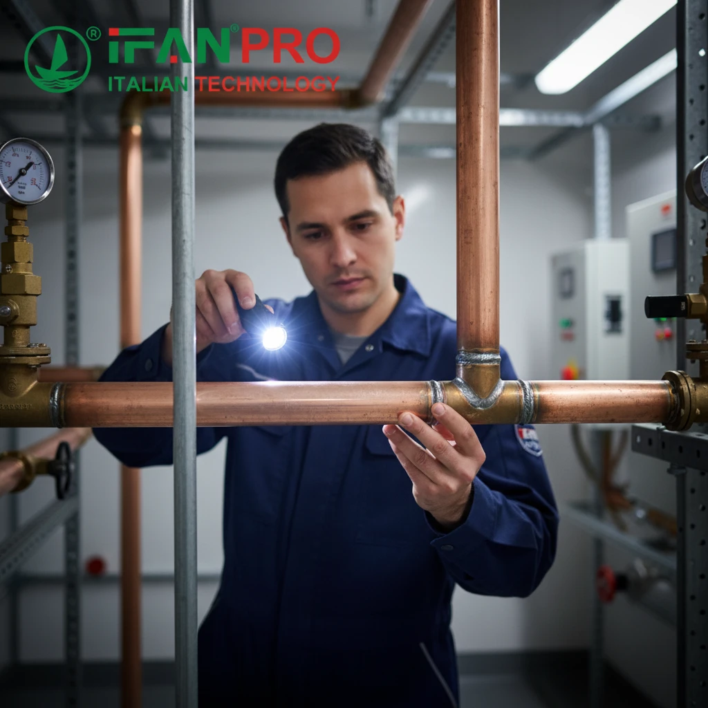
The Visual Inspection: Looking for the Tell-Tale Signs
Your eyes are as important as the gauges. You must inspect every inch of the test section. Look for:
- Active Leaks: Dripping or streaming water. This is an obvious fail.
- Weeping: A slow seepage that forms beads of water on a surface, like at a weld or flange face. This is also a failure, as it indicates a path through the material.
- Bulging or Distortion: Any permanent deformation of a pipe, valve body, or fitting. This indicates the material has yielded (stretched beyond its elastic limit) and is no longer sound.
- Movement: Pipe supports that have shifted or settled excessively under load.
Use a mirror and flashlight to check the backsides of flanges and the tops of pipes. Sometimes, a leak will travel along a thread or surface before dripping, so the source can be hard to find.
Classifying and Responding to Failures
Not all failures are equal. You need to classify them to respond correctly.
A major failure is a rupture, a large leak, or significant deformation. This is an immediate abort. Depressurize the system safely, drain it, and begin a full investigation. The faulty component must be repaired or replaced, and the entire test must be repeated.
A minor failure is a small weep at a flange gasket or a threaded connection. In this case, you may be allowed to depressurize, tighten the connection (torquing bolts to specification), and then repressurize to re-test that specific joint. However, if the weep is on a welded joint, it requires repair (grinding and re-welding) and a full re-test.
Always document everything. Take photos of any failures, record exact pressure and temperature readings, and note the location of any issues. This record is crucial for the repair team and for the final system certification.
Conclusión
A successful hydrostatic test is a milestone, proving your piping system is ready for safe, reliable service. By respecting the process and prioritizing safety, you turn a mandatory check into a cornerstone of quality.


Comentarios recientes