
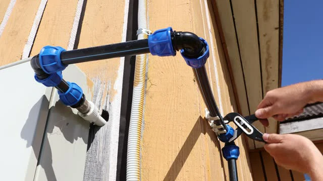
Every HDPE pipe pressure rating you have ever read off a datasheet carries a hidden condition: it is true at 20 C, in clean water, on straight pipe. Move any one of those three and the number moves with it. That is the part most SDR charts leave out, and it is the part that decides whether a line specified as PN16 is still PN16 four years into service in a Gulf pump station or a Nigerian irrigation scheme.
The relationship itself is not mysterious. A pipe’s rating comes out of one equation with three inputs — the resin’s minimum required strength, the wall geometry expressed as SDR, and a design coefficient that most buyers never see named. PE100 at SDR11 gives exactly 16 bar because 20 × 10 divided by 1.25 × 10 is 16, and for no other reason. Once you can run that arithmetic, a supplier’s pressure claim stops being something you accept and starts being something you check.
Key takeaways
- The rating equation is MOP = 20 × MRS / (C × (SDR − 1)), giving bar when MRS is in MPa. Everything on an SDR/PN chart falls out of it.
- C is the design coefficient, 1.25 for water under ISO 4427. It is a divisor on strength, not a bonus — PE100’s 10.0 MPa MRS becomes 8.0 MPa of usable design stress.
- PE80 and PE100 differ only in MRS — 8.0 vs 10.0 MPa under ISO 12162. Same SDR11 wall gives PN12.5 in PE80 and PN16 in PE100.
- Above 20 C the rating falls. ISO 13761:2017 reduction factors for PE100 run 0.92 at 25 C, 0.85 at 30 C, 0.79 at 35 C, 0.73 at 40 C and 0.63 at 50 C.
- Sustained heat costs design life as well as pressure: PIPA POP013 pairs 100 years at 20 C with 50 years at 40 C and 22 years at 50 C for PE100.
- Injection-moulded and electrofusion fittings are not derated — they carry their own marked PN. Fabricated segmented bends and tees are, at 0.8 and 0.5 respectively.
- PE100-RC does not raise the pressure class. Same 10.0 MPa MRS; the premium buys slow-crack-growth resistance, not bar.
What a PN Rating Actually Promises
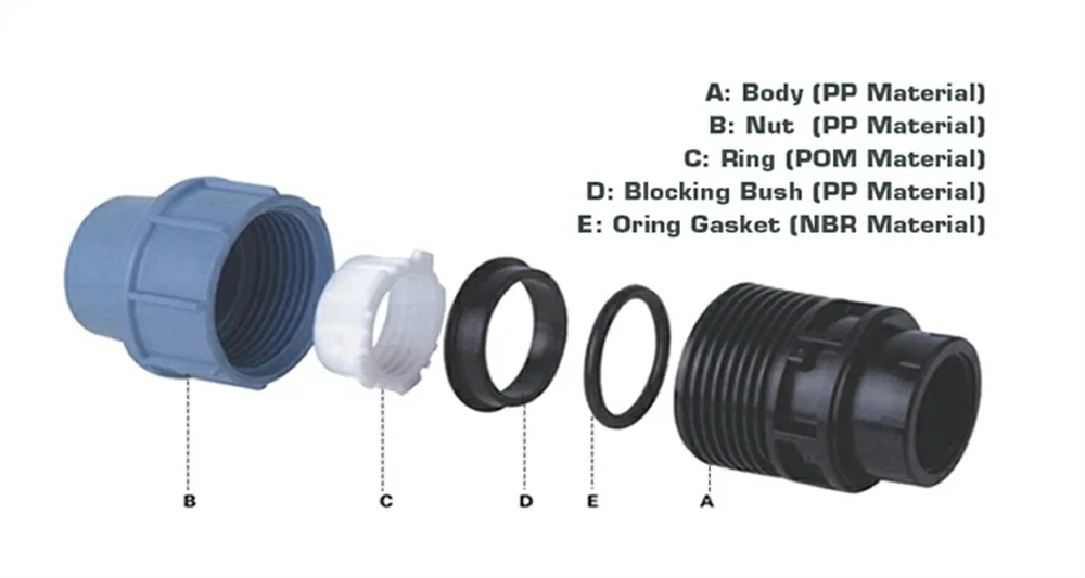
PN is short for pressure nominal, and the number after it is the maximum operating pressure in bar that the pipe will sustain continuously — at 20 C, conveying water, for the design lifetime the resin was classified against. A PN16 pipe holds 16 bar, which is 160 metres of head or 1.6 MPa. None of that is controversial. What catches buyers out is how narrow the conditions attached to it are.
The 20 C reference is not a convenience. It is the temperature at which the resin’s minimum required strength is defined in the first place, so every PN on every PE datasheet inherits it. The Plastics Industry Pipe Association of Australia puts the point plainly in its compound guideline: 20 C is the temperature at which the MRS of the PE compound is defined, and because most PE pipelines run at or below that, most designs need no rerating at all. The exceptions are the ones that matter to anyone buying for a hot climate — above-ground pipelines, bore water, and process lines.
The three conditions hiding inside the number
- Temperature: 20 C wall temperature, not air temperature and not fluid temperature at the pump.
- Fluid: water. Other incompressible fluids need the designer to assess their effect on the PE system separately, and the rerating factors published for water are explicitly not for use with compressed air or gas.
- Component: straight pipe. A fabricated bend or tee welded from pipe segments is a different animal with its own derating, covered further down.
There is a fourth condition that is easy to miss because it is expressed as a lifetime rather than a caveat. The MRS underlying a PN is a 50-year extrapolation. When a supplier quotes “100-year service life” alongside a PN figure, those are two different claims resting on different assumptions, and only one of them is what the pressure class certifies.
The Equation Behind Every SDR/PN Chart
SDR is the standard dimension ratio: nominal outside diameter divided by nominal minimum wall thickness, or SDR = dn/en. It is pure geometry, which is why it behaves the way it does — a higher SDR means a thinner wall at any given diameter, and the ratio holds regardless of size. A 63 mm SDR11 pipe and a 630 mm SDR11 pipe in the same resin carry the same pressure class, because pressure capacity in a thin-walled cylinder depends on the proportion of wall to diameter, not the absolute wall.
The bridge from that geometry to a pressure rating is Lamé’s hoop-stress relationship for thick-walled cylinders, which the PE100+ Association sets out as σ = P(dn − en) / 2en. Substituting SDR gives the cleaner form σ = P(SDR − 1) / 2. Set that hoop stress equal to the material’s design stress — which is the MRS divided by the design coefficient C — and rearrange:
MOP = 2 × MRS / (C × (SDR − 1)) — MRS and MOP in MPa
MOP = 20 × MRS / (C × (SDR − 1)) — MRS in MPa, MOP in bar
Run it for PE100 at SDR11 and water service: 20 × 10 divided by 1.25 × (11 − 1) equals 200/12.5, which is 16 bar. That is where PN16 comes from. Every other row of every SDR/PN chart is the same arithmetic with a different SDR, and the reason the classes land on tidy numbers like 6, 10, 16 and 20 is that the SDR series was chosen to make them do so.
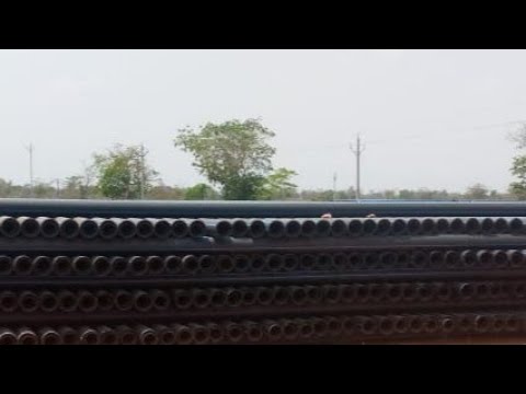
The PE100 SDR series and where the classes land
| SDR | PE100 (MRS 10.0), C = 1.25 | PE80 (MRS 8.0), C = 1.25 | Wall as share of OD |
|---|---|---|---|
| 7.4 | PN25 | PN20 | 13.5% |
| 9 | PN20 | PN16 | 11.1% |
| 11 | PN16 | PN12.5 | 9.1% |
| 13.6 | PN12.5 | PN10 | 7.4% |
| 17 | PN10 | PN8 | 5.9% |
| 21 | PN8 | PN6.3 | 4.8% |
| 26 | PN6.3 | PN5 | 3.8% |
| 33 | PN5 | PN4 | 3.0% |
| 41 | PN4 | PN3.2 | 2.4% |
SDR 7.4, 9, 11, 13.6, 17, 17.6, 21, 26, 33 and 41 are the series the PE100+ Association lists as available in PE100, though not all are stocked everywhere — SDR 17.6 in particular is a regional preference rather than a global one. If you need the OD and wall-thickness dimensions that go with these ratios rather than the pressure classes, our HDPE pipe size and dimension reference carries the metric and IPS tables side by side.
What the Design Coefficient C Is Really Paying For
C is the term that almost never appears in a supplier’s SDR chart, and it is the one doing the most work. It is a divisor applied to the resin’s minimum required strength to arrive at the design stress the pipe is actually allowed to see. For PE100 water applications, C is 1.25, so a resin certified at 10.0 MPa is designed against 8.0 MPa. A quarter of the material’s certified strength is deliberately not used.
That margin is not padding against manufacturing sloppiness. The MRS is already a conservative figure — the 97.5% lower prediction limit of a stress-rupture regression, rounded down to the next lower value in the standard number series. C sits on top of that to absorb the things the regression cannot model: surge and water hammer, installation damage, point loading from backfill, ovality from coiling, and the ordinary uncertainty of a system that must run for decades without inspection.
When C is not 1.25
The PE100+ Association’s own SDR/MOP calculator offers exactly two values for the factor of safety: 1.25 and 1.6. The higher figure is the one applied to gas distribution, where the consequence of a failure is categorically different from a wet one. The arithmetic consequence is worth internalising before you compare quotations across applications: the same PE100 SDR11 pipe that is PN16 for water is 20 × 10 / (1.6 × 10) = 12.5 bar for gas. Nothing about the pipe changed. The permitted operating pressure dropped 22% because the design coefficient did.
If a quotation states a PN without stating the service and the design coefficient behind it, you have a number, not a specification. Ask which C was applied.
This is also where local codes diverge from the ISO route without contradicting it. North American practice does the same job with different vocabulary — a hydrostatic design basis divided by a design factor to give a hydrostatic design stress — which is why a US datasheet talks about DR and psi where an ISO one talks about SDR and bar. The logic is identical; only the constants and units differ, and mixing the two systems mid-specification is a reliable way to order the wrong wall.
PE80 vs PE100: The Same Wall, Two Pressure Classes
The designations PE80 and PE100 are classifications of long-term strength under ISO 12162, and the number is a direct reading of the MRS in units of 0.1 MPa. PE80 means an MRS of 8.0 MPa. PE100 means 10.0 MPa. There is no other difference encoded in the name — not wall thickness, not diameter, not colour.
The classification is earned rather than declared. Long-term pressure tests are run and regressed under ISO 9080 to predict the minimum strength at 20 C and 50 years, and the resulting 97.5% lower prediction limit is rounded down to the next smaller value in the R10 or R20 series. A compound landing anywhere from 10.0 up to just under 11.2 MPa is classified PE100 — meaning a genuine PE100 may have real strength above its label, but never below it.
Feed the two MRS values through the rating equation at the same SDR11 and the commercial stakes become obvious. PE100 gives 16 bar; PE80 gives 20 × 8 / (1.25 × 10) = 12.8 bar, which is classed as PN12.5. A pipe substituted from PE100 to PE80 without a wall change loses exactly 20% of its rating while looking identical on delivery. To hold PN16 in PE80 you must drop to SDR9, which is a materially thicker and heavier pipe.
Where PE100-RC fits, and what it does not do
PE100-RC carries the same 10.0 MPa MRS as conventional PE100, so it produces exactly the same PN at the same SDR. The RC premium buys resistance to slow crack growth, and the test requirement is where you can see the size of the difference: the ISO 13479 notched pipe test asks for more than 500 hours from conventional PE100 and more than 8,760 hours from PE100-RC. That is a survival requirement roughly seventeen times longer.
Practically, that buys installation freedom rather than pressure. PE100-RC is what allows trenchless installation by directional drilling and open-trench laying with no sand bed using the excavated soil directly as backfill — the installations where point loads and surface notches would otherwise be the failure mechanism. If a supplier prices PE100-RC as a higher pressure class, the specification is being misrepresented.
Reading a Derating Table Without Getting It Backwards
Here is where most of the derating tables circulating online cause real damage: some publish a multiplier, some publish a divisor, and almost none say which. A table showing “1.2” at 35 C is not telling you the pipe gets 20% stronger. It is a design factor you divide by. A table showing “0.79” at the same temperature is the reciprocal expressed as a multiplier. Both are correct; applying one as if it were the other is a 50% error in the wrong direction.
The check that resolves it takes five seconds and needs no reference at all: a derating number below 1.0 is a multiplier, and a number above 1.0 is a divisor. Both routes land in the same place. PIPA’s design factor of 1.2 at 40 C and the ISO multiplier of 0.73 are describing one physical fact — 1/1.2 is 0.83, and the residual gap between 0.83 and 0.73 is the difference between a rounded engineering factor and the underlying regression, with the lower figure being the conservative one.
The authoritative multiplier set for PE100 comes from ISO 13761:2017, which specifies the method for deriving pressure reduction factors for PE systems operating above 20 C. The PE100+ Association publishes the resulting factors directly:
| Wall temperature | ISO 13761:2017 reduction factor (PE100 & PE100-RC) | PN16 pipe becomes | PN10 pipe becomes |
|---|---|---|---|
| 20 C | 1.00 | 16.0 bar | 10.0 bar |
| 25 C | 0.92 | 14.7 bar | 9.2 bar |
| 30 C | 0.85 | 13.6 bar | 8.5 bar |
| 35 C | 0.79 | 12.6 bar | 7.9 bar |
| 40 C | 0.73 | 11.7 bar | 7.3 bar |
| 45 C | 0.67 | 10.7 bar | 6.7 bar |
| 50 C | 0.63 | 10.1 bar | 6.3 bar |
Why the tables you find online disagree
Search this topic and you will collect three or four derating tables that do not match, which is corrosive to a specifier’s confidence and usually blamed on someone being wrong. Mostly they are not. They come from different documents with different scopes, and knowing which is which tells you whose number to use.
The North American figures descend from the older ISO 13761:1996 lineage and are quoted in Fahrenheit — the Plastics Pipe Institute set runs 1.00 at 73 F, 0.94 at 80 F, 0.86 at 90 F and 0.78 at 100 F. Read 100 F as 38 C and compare against the ISO 13761:2017 row at 40 C, which is 0.73. The two systems correlate closely but the 2017 revision is slightly more conservative, so a US-sourced table applied to a metric design will give you a marginally optimistic answer. That is fine when you know it and dangerous when you do not.
Then there are the tables that match neither. One page currently ranking for this query publishes 0.93 at 25 C, 0.87 at 35 C and 0.82 at 45 C, against ISO 13761:2017’s 0.92, 0.79 and 0.67. At 45 C that is a 22% overstatement of allowable pressure, on a page carrying no citation for where the numbers came from. The rule that protects you is simple and worth applying to any supplier document: a derating table without a named source standard is not usable, because you cannot tell whether you are looking at ISO 13761:2017, its 1996 predecessor, a national code, or a compound-specific manufacturer curve.
A fourth legitimate source deserves naming because it will also disagree with the generic tables: an individual resin producer’s own data. PIPA notes that its factors were derived from ISO 9080 stress-rupture testing on specific listed compounds, and that where a compound has not demonstrated conformity you fall back to the generic national tables instead. A manufacturer offering a better factor than ISO 13761 for a named grade may be entirely correct — but the burden is on them to show the test data, and ISO 4427-3 makes that explicit for fittings by requiring objective evidence before an alternative factor may be claimed.
One footnote on the ISO table is worth carrying into a specification argument: EN 12201-1:2024 states 0.62 at 50 C rather than 0.63. The gap is trivial in engineering terms and useful in commercial ones, because a supplier quoting 0.62 is working from the current European standard and a supplier quoting 0.63 is working from ISO 13761:2017. Neither is wrong. A supplier who cannot say which document their factor came from is the one to worry about.
What Heat Costs You in Years, Not Just Bar
Derating the pressure is only half the story, and it is the half that gets published. The other half is that sustained temperature also shortens the design life the rating was extrapolated against. PIPA’s POP013 guideline is unusually honest about this because it prints both columns in the same table — the design factor and the minimum life it corresponds to.
| Temperature | PE100 design factor (divisor) | PE100 minimum life | PE80B minimum life |
|---|---|---|---|
| 20 C | 1.0 | 100 years | 100 years |
| 30 C | 1.1 | 100 years | not stated |
| 40 C | 1.2 | 50 years | not stated |
| 50 C | 1.4 | 22 years | 36 years |
| 60 C | 1.5 | 7 years | 12 years |
| 80 C | 2.0 | 1 year | 1 year |
Read the two right-hand columns against each other and something counterintuitive appears. At 50 C and 60 C, PIPA’s tables give PE80B the longer minimum life — 36 years against PE100’s 22, and 12 years against 7. The stronger resin at ambient is not automatically the longer-lived resin when hot. That is a consequence of how each compound’s stress-rupture regression behaves at elevated temperature, and it is the sort of thing that only shows up if you look at the source tables rather than a summarised chart. For a heated process line, “specify PE100 because it is better” is not an argument that survives contact with the data.
Which temperature you are supposed to use
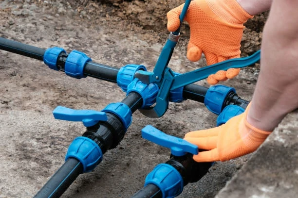
The rating depends on pipe wall temperature, and POP013 permits three ways to establish it. You can assume a constant wall temperature typical of continuous service, which is what a buried cold-water main gets. You can compute a time-weighted average where variation is predictable, using Tm = T1L1 + T2L2 + … + TnLn, where each L is the proportion of service life spent at that temperature. Or, where variation is large and unpredictable — the case for above-ground irrigation mains — you take the maximum service temperature minus 10 C, capped at 80 C.
That third method is the one that catches out buyers specifying for hot climates, because it is deliberately blunt and it does not let you average away the afternoon. There is a related trap worth naming: where a temperature differential exists across the wall, the material temperature is the mean of the inside and outside surface temperatures — but the standard tells you to also check the stopped-flow condition, because when a line stands still the fluid and ambient temperatures equalise and the favourable average disappears. Our note on how HDPE handles UV exposure covers the surface side of the same above-ground problem.
Fittings Derate Differently From Pipe
A pressure system is rated at its weakest component, and on HDPE lines that is rarely the pipe. It is worth knowing exactly which components carry a derating and which do not, because the rule is cleaner than the folklore around it suggests. PIPA POP006, which implements ISO 4427-3, states it directly: butt-welded straight or coiled pipe lengths are not derated and operate at the rated pressure of the pipe; electrofusion joints and fittings and injection-moulded fittings have design pressure ratings marked on them and operate at their stated rating, with no derating applied.
What does get derated is fabricated fittings — bends and tees welded up from cut pipe segments rather than moulded in a tool. These are common in large diameters where moulding is uneconomic, and the factors are substantial:
| Component | Derating factor at 20 C | Effect on a PN16 line |
|---|---|---|
| Straight / coiled pipe, butt welded | none | 16 bar |
| Injection-moulded fitting (marked PN) | none — use the marked PN | its own marked rating |
| Electrofusion fitting | none — use the marked PN | its own marked rating |
| Segmented bend, cut angle ≤ 7.5° | 1.0 | 16 bar |
| Segmented bend, cut angle 7.5° to 15° | 0.8 | 12.8 bar |
| Fabricated segmented tee / pulled branch tee | 0.5 | 8 bar |
A fabricated tee at 0.5 halves the system. A network designed at PN16 with fabricated tees at every branch is, in the eyes of the standard, a PN8 network — and cut angles above 15 degrees are not permitted at all. This is the single most expensive thing on this page to get wrong, because the pipe invoice will say PN16 throughout and nothing on site will look unusual.
The two derating families also stack. POP006 specifies its factors for fittings operated up to 20 C and states that above 20 C additional temperature derating is required on top. A fabricated tee at 0.5 on a line running at 40 C takes the 0.73 as well: 16 × 0.5 × 0.73 is 5.8 bar from a pipe sold as PN16.
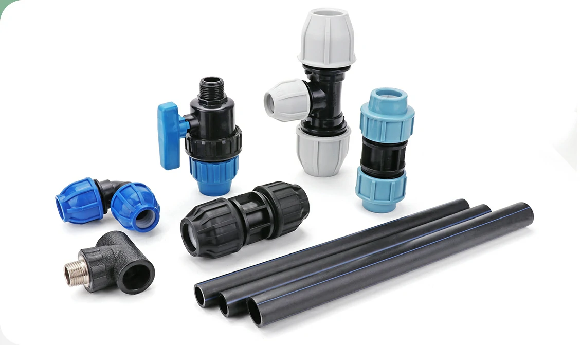
The practical procurement move follows from the table rather than from any sales argument: on a hot or high-pressure line, prefer moulded and electrofusion components over fabricated ones wherever the diameter allows, and require the marked PN on each item. IFANPRO’s HDPE fittings range is moulded rather than fabricated — 37 catalogue items covering the 606-series valves, tees, elbows and caps alongside the 601 to 604 socket, tee, elbow and plug series — which puts all of them in the no-derating column.
Be aware of the limit on what that catalogue currently tells you: only the saddle clamps publish a pressure class on the listing, at PN10. For every other item the marked rating is a question to ask before you build it into a pressure calculation. See also our comparison of butt fusion, electrofusion and compression jointing for how the joint method itself changes what you can specify.
A Worked Derating Check You Can Reuse
Take a real specification problem: an above-ground irrigation main in a hot region, PE100 SDR11 quoted as PN16, peak ambient 48 C, with fabricated tees at the branch points and a required working pressure of 9 bar. The quotation says PN16 and the requirement says 9 bar, so it looks like a comfortable margin. Work it through in order.
Step by step
- Confirm the base rating from first principles. PE100, MRS 10.0, C 1.25 for water, SDR11: 20 × 10 / (1.25 × 10) = 16 bar. The quotation checks out at 20 C.
- Establish the design wall temperature. Large unpredictable variation above ground, so the method is maximum service temperature minus 10 C: 48 − 10 = 38 C.
- Apply the temperature reduction factor. 38 C sits between the 35 C and 40 C rows, so take the conservative 40 C figure of 0.73: 16 × 0.73 = 11.7 bar.
- Apply the component derating. Fabricated tees at 0.5: 11.7 × 0.5 = 5.8 bar at the branches, while the straight runs stay at 11.7 bar.
- Compare against the requirement. The line needs 9 bar. The straight pipe passes. The tees fail by a wide margin, and they are what sets the system rating.
The fix is not a thicker pipe, which is where this usually goes wrong on site. Moving to SDR9 lifts the pipe to PN20 and the derated straight run to 14.6 bar, but the tees only reach 7.3 bar and the system still fails. Switching the branches to moulded or electrofusion tees removes the 0.5 factor entirely and the system clears 9 bar on the original SDR11 pipe. The component choice was worth more than a whole pressure class of wall.
What to put in the enquiry
If you send a supplier only a diameter and a PN, you will get a quotation that is correct at 20 C and possibly useless at yours. Five lines make the difference: the resin grade and MRS, the SDR, the design coefficient the PN assumes, the design wall temperature with the method used to derive it, and the fitting construction at every branch. A supplier who answers all five is quoting a system; one who answers only the first two is quoting a price.
Expect the commercial terms to be quoted against that spec rather than published ahead of it, and treat any supplier who does otherwise with some suspicion. Minimum order quantity on moulded HDPE fittings is normally set per size and per mould rather than as one headline figure, so it moves with how many distinct items your size mix contains — a single-size order and a twelve-size order of the same total volume are not the same production job. Lead time is driven by the same thing plus whether the sizes are stock or scheduled. Pricing follows resin cost, which is a traded commodity, so a figure quoted more than a few weeks ago is indicative rather than firm.
On verification, the useful thing to ask for at enquiry stage is documentary rather than physical: the marked PN on each fitting item, and the certification held against your destination market. IFANPRO holds ISO 9001 and ISO 14001 along with CE, WRAS, NSF/IAPMO, Intertek, EAC, Watermark and SAI Global marks across its range — but which certificate covers which specific HDPE item is a question to put in writing rather than to infer from a company page, because scope is per product family and per market, and no supplier’s summary list is a substitute for the certificate itself.
What to Check on the Documents Before You Accept a PN
Everything above is checkable from paperwork, before anything is shipped. This is the documentary sequence that catches a mis-stated pressure class, and it is deliberately ordered so the cheapest checks come first.
- Recompute the PN from the SDR yourself. One line of arithmetic. If the quoted PN does not equal 20 × MRS / (C × (SDR − 1)), either a different C is in play or the number is wrong, and both are worth an email.
- Check that the resin grade is stated as a grade, not a description. “PE100” is a classification with an MRS behind it. “High-quality HDPE” and “100% virgin PE” are not, and neither supports a pressure calculation.
- Ask which standard the derating table came from. ISO 13761:2017, its 1996 predecessor, EN 12201-1:2024 and a compound-specific curve are all legitimate answers. “Industry standard” is not one.
- Confirm the marking on the fittings, item by item. Moulded and electrofusion fittings carry their own PN, and that marked figure is what your system is rated to — not the pipe’s.
- Identify any fabricated component in the bill of materials. Segment-welded bends and tees carry the 0.8 and 0.5 factors. If large-diameter bends are quoted without a construction method stated, ask before you price the alternative.
- Match the certificate to the item and the market, not to the company. A supplier holding WRAS, NSF/IAPMO or Watermark holds it for defined product families in defined markets. Ask for the certificate covering the items on your order.
Where this page stops: it does not size the pipe hydraulically, cover surge analysis, or address buried-pipe structural loading, all of which sit alongside pressure class in a real design and none of which the SDR/PN relationship answers.
Заключение
Pressure class in HDPE is not a property you buy, it is a result you calculate — from resin strength, wall geometry, a design coefficient, the service temperature and the components you join it with. The chart on a supplier’s website is that calculation frozen at 20 C on straight pipe, which is a fair starting point and a poor finishing one for anything running hot or branching often.
If you are specifying now, the highest-value thing you can do is re-run your line at its real design wall temperature and check what the branch components do to it. When you have that number and a size list, you are in a position to compare quotations on the same basis rather than on the label.
Frequently Asked Questions
What is the pressure rating of SDR11 HDPE pipe?
In PE100 with the water design coefficient of 1.25, SDR11 gives 16 bar — PN16. The same SDR11 wall in PE80 gives 12.8 bar, classed PN12.5, because PE80’s MRS is 8.0 MPa rather than 10.0.
Does HDPE pipe pressure rating change with diameter?
No. SDR is a ratio of diameter to wall thickness, so a 63 mm and a 630 mm pipe at the same SDR and resin grade carry the same PN. Only the absolute wall thickness changes.
How much pressure does HDPE lose at 40 C?
ISO 13761:2017 gives a reduction factor of 0.73 for PE100 at 40 C, so a PN16 pipe is limited to 11.7 bar. PIPA’s tables also cut the expected minimum life from 100 years to 50 at that temperature.
What does the design coefficient C do?
It divides the resin’s MRS to give the allowable design stress. At C = 1.25 for water, PE100’s 10.0 MPa becomes 8.0 MPa. Gas service uses 1.6, which drops the same SDR11 pipe from 16 bar to 12.5.
Do HDPE fittings need derating too?
Injection-moulded and electrofusion fittings are not derated — use the PN marked on them. Fabricated segmented bends take 0.8 above a 7.5 degree cut angle, and fabricated tees take 0.5.
Is PE100-RC rated for higher pressure than PE100?
No. Both have an MRS of 10.0 MPa and the same PN at a given SDR. PE100-RC buys slow-crack-growth resistance — over 8,760 hours in the ISO 13479 notched pipe test against over 500 for standard PE100.
Which temperature should I use for derating?
Pipe wall temperature, not air or fluid temperature. For above-ground lines with large unpredictable swings, PIPA POP013 directs you to take the maximum service temperature minus 10 C, capped at 80 C.









 Русский
  English
  Français
  Español
Последние комментарии