
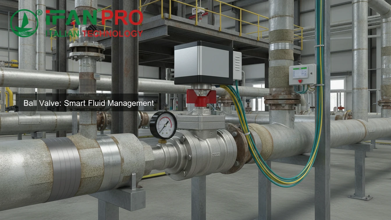
We recently helped a factory manager upgrade his old piping without a long shutdown. His main fear was disrupting production, so we focused on a simple, phased integration plan.
You can integrate a smart ball valve by focusing on its three key connection points: power, communication, and the pipe itself. Most valves use standard interfaces, allow for inline retrofitting, and connect to common control software through straightforward configuration, all of which minimizes system downtime.
The process is more manageable when broken down. Let’s address the key questions step by step.
What Are the Standard Electrical and Communication Connection Interfaces?
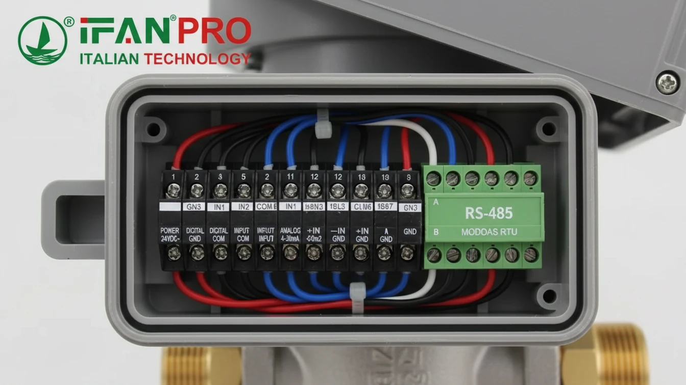
Opening a valve box to find a confusing mess of wires is a common headache. Fortunately, most modern smart valves adhere to well-established standards.
The standard electrical interface is typically 24V DC or 110/220V AC power. For communication, common options include 4-20mA analog signals, basic On/Off digital signals, and digital protocols like Modbus RTU, Profibus, or BACnet for direct integration into control networks.
Powering the Valve Actuator
First, the valve needs a reliable power source. Most smart ball valves use low-voltage direct current (DC) because it is safe and compatible with standard industrial control panels.
- 24V DC: This is the most common standard. It is safe for personnel and aligns with most PLC (Programmable Logic Controller) system outputs.
- 110/220V AC: Some larger valves or those for specific building systems might use alternating current (AC) power.
Critical First Step: Always check the valve’s nameplate or data sheet first. Providing incorrect power can permanently damage the actuator.
Establishing Communication
Once powered, the valve needs to receive commands and send back status. Communication methods range from simple to advanced.
1. Basic Analog & Digital Signals:
This is the simplest method, using elementary signals for control.
- 4-20mA Analog Control: A prevalent industrial standard. For instance, a controller might send a 4mA signal to command “close” and a 20mA signal for “open.”
- Digital On/Off (Dry Contact): Here, the control system uses a simple relay switch, similar to a light switch, to send a discrete “Open” or “Close” command.
2. Digital Fieldbus Protocols:
For deeper integration, digital protocols allow one cable to connect multiple valves and exchange rich data like position, torque, and fault codes.
| Protocol | Common Use | Key Advantage |
|---|---|---|
| Modbus RTU | Industrial automation | Extremely popular, simple, and nearly universally supported. |
| Profibus DP | Factory automation | Enables high-speed communication for complex systems. |
| BACnet MS/TP | Building Automation (HVAC) | The standard protocol for building management systems. |
3. Modern Connectivity Options:
Newer valves may offer Ethernet/IP, PROFINET, or wireless options like LoRa for connection to IoT platforms.
Practical Advice: Before ordering, audit your existing control panel. Identify a spare power source and check what communication cards your PLC has. This audit will directly determine the correct valve model to purchase.
Is Retrofitting Possible Without Replacing the Entire Pipeline System?
The idea of cutting out extensive old piping often halts upgrade projects. However, a full replacement is rarely necessary.
Yes, retrofitting is a core design feature. Smart ball valves are typically installed as “inline” components. This means you can cut out a section of the existing pipeline and install the valve between two flanges or threaded unions, leaving the rest of the system unchanged.

The Inline Replacement Strategy
The goal is to replace only a specific section of pipe or an old manual valve. This targeted approach confines the work to a single point.
Step-by-Step Retrofit Process:
- Isolate and Drain: First, safely isolate the pipeline section. Close existing upstream and downstream valves, then drain the fluid from that segment.
- Cut and Remove: Next, cut out the pipe section slated for replacement, whether it’s a plain spool or a faulty manual valve.
- Measure and Match: This is the most critical step. Ensure the new smart valve matches the existing system’s:
- Pipe Size (Diameter): e.g., 1 inch, 2 inch, DN25, DN50.
- Connection Type: Threaded ends, flanges, or compression fittings must align perfectly.
- Pressure Rating: The valve’s rating must meet or exceed the system’s maximum operating pressure.
- Install and Connect: Finally, fit the new valve into the gap using proper gaskets and bolts, then run the electrical and communication cables to the control panel.
Key Considerations for a Smooth Retrofit
While mechanically straightforward, successful retrofitting requires planning for a few key factors:
- Space: The smart valve’s actuator is larger than a manual handle. Verify there is enough physical space and clearance for it to operate.
- System Shutdown: A planned shutdown is necessary. However, its duration can be minimized with good planning for isolating the specific pipeline section.
- Bypass Lines: For absolutely critical processes, engineers may install a temporary bypass line. This allows the main process to continue during the valve installation.
Solved Pain Point: A food plant had a leaking manual valve in a critical cooling line. They dreaded a week-long shutdown. We supplied a flanged smart valve with the exact same bolt pattern and face-to-face dimensions. Their team installed it during a scheduled 8-hour maintenance window without modifying any other pipes.
How Do You Configure the Valve with Existing Control Software?
Physical installation is only half the task. The other half is making the valve communicate effectively with your control room software.
You configure the valve by setting its communication parameters to match your network, mapping its functions to specific software registers, and then testing the commands. Because most integrations use standard protocols, this is primarily a software setup task rather than complex custom programming.
The Configuration Workflow
Think of this process like adding a new network printer: assign an address and install the driver.
Step 1: Physical Network Integration
For digital protocols like Modbus, connect the valve’s communication wires to the network. Then, set a unique device address on the valve, usually via a dial or software tool. This unique address prevents communication conflicts on the network.
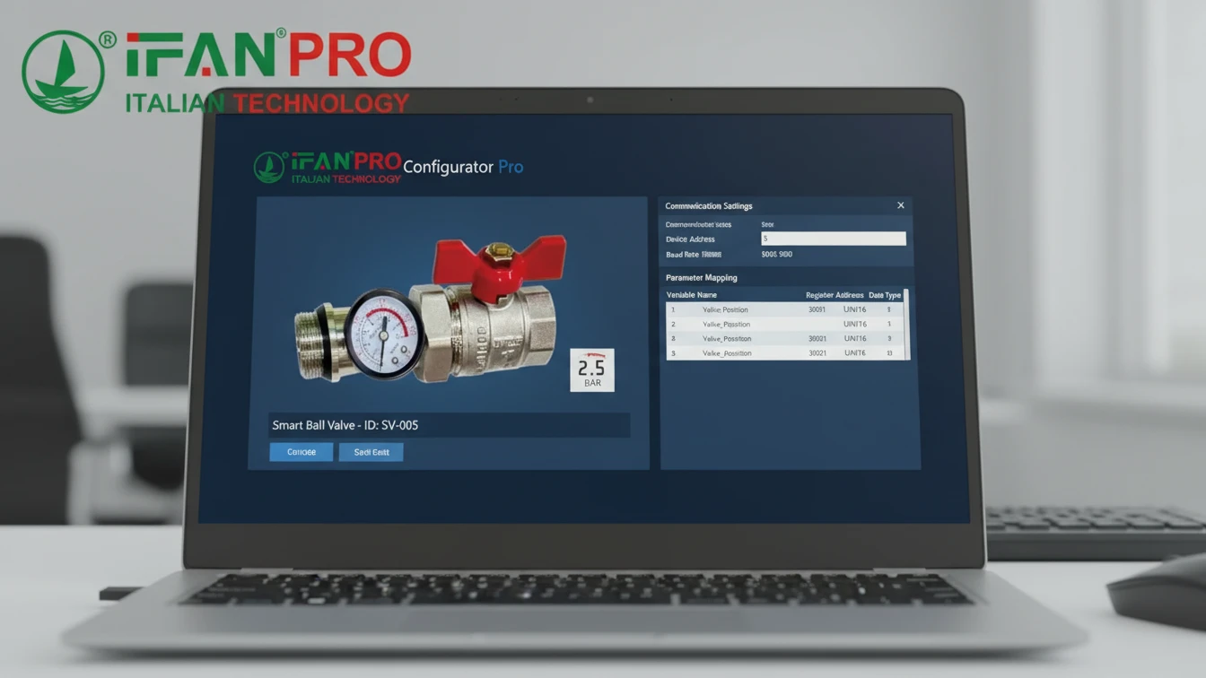
Step 2: Software Setup and Register Mapping
This work is done within your existing control software (e.g., Siemens TIA Portal, Allen-Bradley Studio 5000, or SCADA systems like Ignition).
- Add the Device: Inform your software that a new device (e.g., “Modbus device address 5”) is on the network.
- Import the Register Map: Every smart valve has a “Register Map” or “Protocol Manual.” This document is the valve’s dictionary, listing numerical addresses (registers) that control specific functions.
- Example: Holding Register 40001 might control the target position (write 0 to close, 100 to open).
- Example: Input Register 30001 might report the current valve position (a value from 0 to 100).
- Map the Registers: In your control software, link these register addresses to internal tags or variables. For instance, create a software tag called
Cooling_Valve_Commandand link it to the valve’s command register 40001.
Essential Configuration Table
Below is a simplified example of a configuration table for a Modbus-based valve.
| Function | Register Type | Register Address | Data Format | Software Tag Name |
|---|---|---|---|---|
| Command Valve | Holding Register | 40001 | 0=Close, 100=Open | VLV_101_CMD |
| Read Position | Input Register | 30001 | 0-100% | VLV_101_POS |
| Read Status | Input Register | 30002 | Bit 0=Open, Bit 1=Closed, Bit 2=Fault | VLV_101_STATUS |
| Reset Fault | Coil | 00001 | Write 1 to reset | VLV_101_RESET |
Step 3: Programming Control Logic
Finally, write or modify the logic in your PLC. A basic example is: “IF temperature >30°C, THEN set the tag VLV_101_CMD to 100.” The software handles the underlying communication.
Proactive Advice: Always request the protocol manual before purchase. Share it with your control engineer to confirm compatibility. A brief review can prevent significant integration delays later.
What Are the Key Steps for Commissioning a New Smart Valve?
Activating a new valve without proper testing is risky. Commissioning is the essential final check for safety and performance.
The key commissioning steps are: 1) A pre-power mechanical check, 2) A “dry” electrical test without system pressure, 3) A slow, supervised first operation under pressure to monitor for leaks, and 4) Final integration into the automated control loop and alarm systems.

The Commissioning Checklist
A structured, phased approach prevents errors. Follow these steps in sequence.
Phase 1: Mechanical & Visual Inspection (System OFF)
Before applying power or pressure, conduct a thorough physical check.
- Verify all pipe connections are tight and properly aligned.
- Ensure the valve actuator is securely mounted.
- Check that the manual override handle is accessible and moves freely.
- Confirm any shipping braces or locks are removed.
Phase 2: Electrical and Functional Test (System OFF / Drained)
With the system safe (drained and isolated), apply electrical power.
- Power Up: Apply the correct voltage and check for indicator lights on the valve.
- Manual Command Test: Use the valve’s local buttons or a test tool to command it to open and close. Observe the actuator for smooth, quiet movement and verify the position indicator changes accordingly.
- Software Test: From your control software, send open/close commands. Confirm the software’s status feedback matches the valve’s actual physical movement.
Phase 3: Initial Operation Under Pressure (Leak Test)
This is the most critical phase. Re-pressurize the system slowly and with caution.
- Slow Pressurization: Open the upstream isolation valve gradually. As pressure builds, carefully inspect all connection points and the valve body for leaks.
- First Cycle: With stable pressure, command the valve to move slowly to 50% open, then 100%, then back to closed. Watch closely for leaks around the stem seals during movement.
- Monitor Performance: Listen for abnormal noises and verify the valve moves at its expected speed.
Final System Integration Table
After the valve proves itself, complete its integration into the broader control system.
| Task | Description | Goal |
|---|---|---|
| Alarm Setup | Program the software to monitor the valve’s fault signals and status bits. | Ensure immediate alerts for jams, overheating, or power loss. |
| Logic Tuning | Adjust control logic timings, like the wait time after a command before checking status. | Make the automation reliable and error-free. |
| Interlock Testing | Test how the valve interacts with other equipment (e.g., pump shutoff sequences). | Prevent dangerous or damaging operational sequences. |
| Documentation | Update all piping diagrams, instrument lists, and control system documentation. | Create a clear record for future maintenance and troubleshooting. |
Common Mistake to Avoid: Never skip the “dry” functional test (Phase 2). Testing the valve’s movement without system pressure allows you to safely identify and fix any electrical or mechanical issues.
Заключение
Integrating a smart valve is a manageable process of matching interfaces, retrofitting inline, configuring software, and careful commissioning. For reliable, easy-to-integrate smart ball valves with comprehensive support, choose ИФАН for your automation upgrade.


Последние комментарии