
We once had a client whose valve failed because of poor support, causing a costly line shutdown. This taught us that proper integration is as critical as the valve itself.
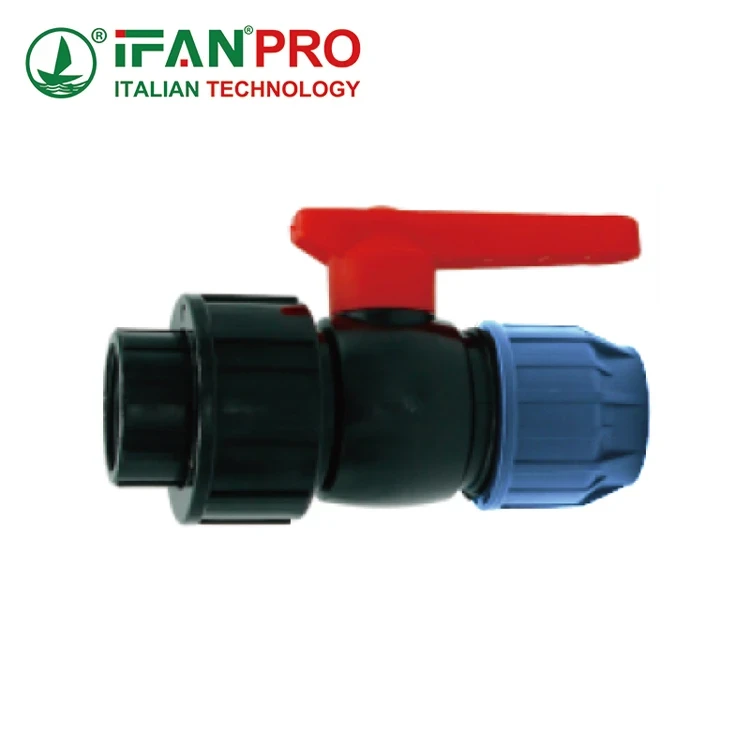
To integrate a female valve (flanged valve) into an HDPE network, you must use flanged adapters. The key steps are: preparing and squaring the pipe ends, heat-fusing HDPE flanged adapters to the pipe, bolting the valve to the adapters with a gasket, and ensuring proper support and alignment throughout to prevent stress on the pipeline.
Let’s break down this process into a reliable, step-by-step guide to ensure a leak-free and long-lasting installation.
What is the Step-by-Step Process to Integrate a Valve into an HDPE Network?
Rushing the fusion process is the most common mistake we see. It leads to weak joints and future leaks.
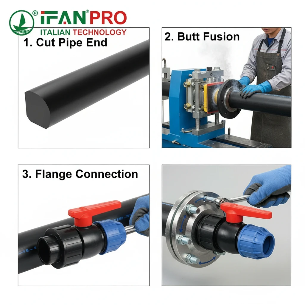
The step-by-step process involves planning, cutting the HDPE pipe squarely, thermally butt-fusing HDPE flanged adapters to each pipe end, allowing proper cooling, and then mechanically bolting the female valve between the two fused adapters using a compatible gasket and correct bolt torque sequence.
Step 1: Planning and Preparation
First, you must plan the job. Gather all parts: the valve, two HDPE flanged adapters, the correct gasket (usually EPDM or Nitrile), stainless steel bolts, nuts, and washers. Ensure the valve and adapters have the same pressure rating (PN) and flange standard (e.g., PN16/ANSI). Then, shut down the line, drain it completely, and make sure the work area is safe and clean.
Step 2: Cutting and Preparing the Pipe
Next, you need to cut the HDPE pipe. You must cut it perfectly straight. Use a dedicated pipe cutter or a saw guide. A crooked cut will cause a bad fusion. After cutting, remove all burrs and clean the pipe end and the adapter’s fusion surface with isopropyl alcohol. Do not touch these clean surfaces afterward.
Step 3: The Critical Fusion Process
Now, perform the butt fusion. This joins the HDPE adapter to the HDPE pipe.
Set up the fusion machine correctly. Clamp the pipe and the adapter securely in the machine. Face off their ends with the facing tool to ensure they are perfectly flat and parallel. Then, bring the two heated plates (one for the pipe, one for the adapter) into contact with them.
Control the heat and pressure. Follow the fusion machine’s manual or the material supplier’s chart for the correct heating time and pressure. This depends on the pipe’s diameter and wall thickness. Do not guess. After the heating time is up, quickly remove the heating plates, bring the molten surfaces together, and apply the fusion pressure. Hold it steady during the specified cooling time. Do not move or stress the joint during cooling.
Step 4: Mechanical Assembly of the Valve
Once both adapters are fused and cooled, you can install the valve. Position the valve between the two flanged adapters. Place the gasket correctly between each flange face.
Follow the correct bolting procedure. Insert the bolts by hand first. Then, tighten the nuts in a criss-cross or star pattern, like tightening a car wheel. Do not tighten one side completely before the other. Use a torque wrench and follow the valve manufacturer’s recommended torque values. This ensures even pressure on the gasket and prevents distortion or leaks.
Key Tools and Materials Checklist
| Item | Purpose | Note |
|---|---|---|
| Butt Fusion Machine | To melt and join HDPE pipe to adapter. | Must be calibrated for the pipe size. |
| Pipe Cutter/Guided Saw | To make a perfectly square cut. | A crooked cut is the #1 fusion flaw. |
| Isopropyl Alcohol & Clean Cloth | To clean fusion surfaces. | Essential for a strong bond. |
| Torque Wrench | To tighten flange bolts evenly. | Prevents gasket failure and flange warping. |
| Calipers/Level | To check alignment. | Misalignment causes stress. |
How Do You Plan the Pipeline Layout for Optimal Valve Placement and Access?
A valve buried or placed in a corner is useless for operation and maintenance. We design for access from day one.
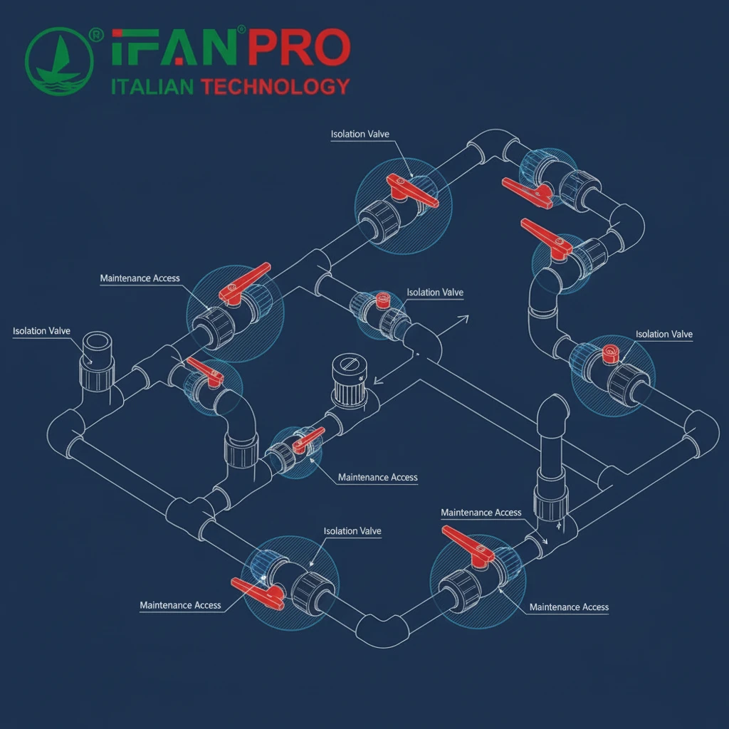
Plan the pipeline layout by placing valves at key isolation points, branches, and before sensitive equipment. Always ensure there is enough clear space around the valve for an operator to turn the handwheel or use an actuator, and for a mechanic to remove bolts or repair the valve in the future without digging up other pipes.
Principles for Strategic Placement
Good planning saves time and money during emergencies. You should place valves with a clear purpose.
First, think about system operation. Install valves to isolate sections for maintenance. For example, place them on both sides of a pump or a filter so you can service that equipment without shutting down the entire line. Also, put valves at major branches to control flow direction.
Second, think about future access. A valve needs physical space. Ask yourself: Can a person reach the valve easily? Can they turn the handwheel fully? If it needs an actuator, is there space for it? Is there room to use a wrench to remove the bolts? We recommend a minimum clearance of 18-24 inches (450-600mm) around the valve.
Avoiding Common Layout Mistakes
Many problems come from poor planning.
- Buried Valves: Never bury a standard valve directly in the ground. Use a valve box or chamber if it must be below grade.
- Obstructed Access: Do not install a valve too close to a wall, another pipe, or a structural beam. This makes it impossible to service.
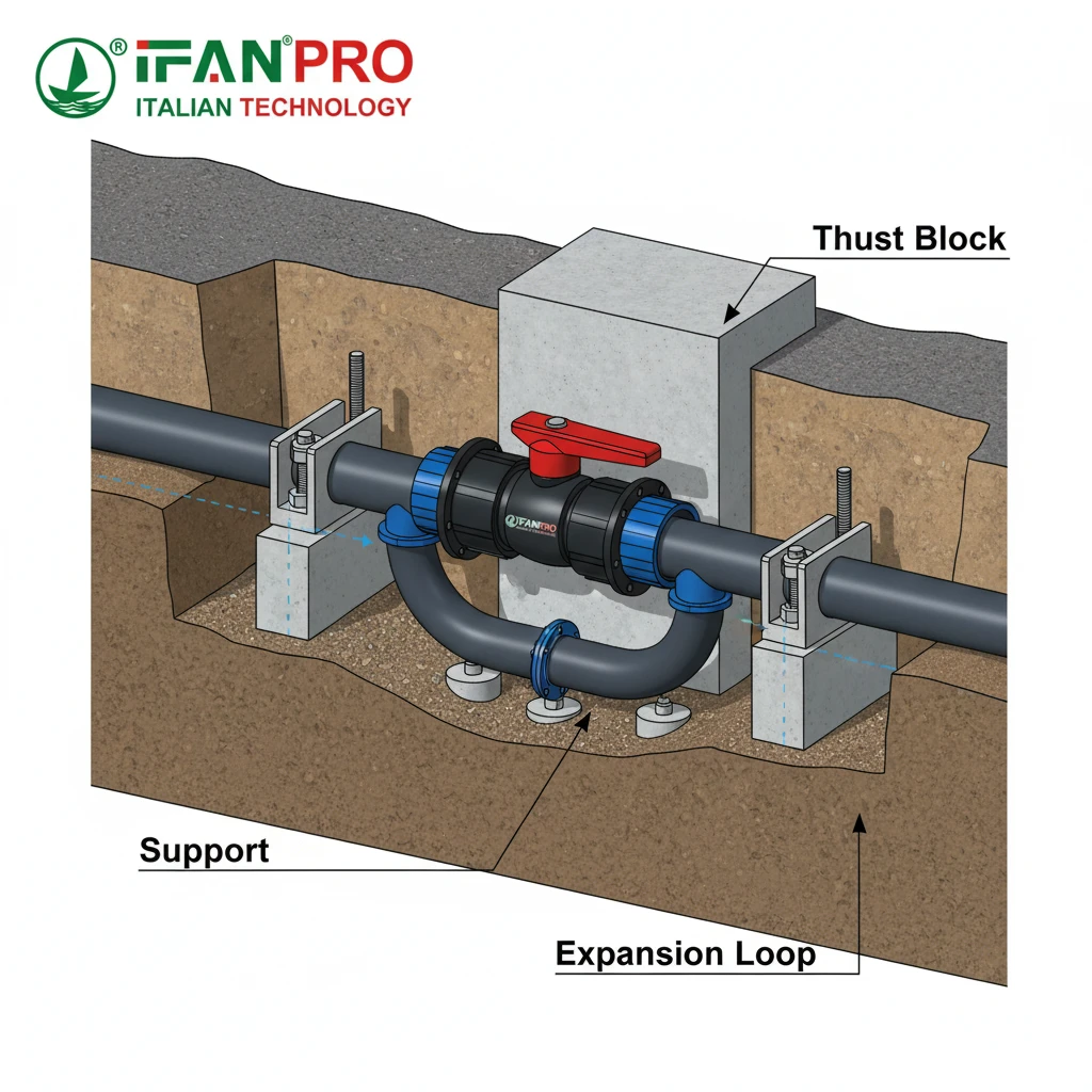
- Unsupported Ends: Remember that a valve is a heavy point in the line. Plan for support structures (like concrete thrust blocks or pipe clamps) on both sides of the valve location before you start welding.
Layout Planning Table
| Valve Purpose | Recommended Placement | Minimum Access Space |
|---|---|---|
| Main Line Isolation | At the start of a major section, near junctions. | Full circumference access for bolt removal. |
| Equipment Protection | Upstream and downstream of pumps, meters, filters. | Enough space to remove the equipment. |
| Drain or Vent Point | At low points (for drain) or high points (for vent). | Space for hose/pipe connection. |
| Управление потоком | On branches where flow needs regulation. | Easy access for frequent handwheel operation. |
Good layout is a mix of engineering and common sense. Always walk the planned route and imagine performing maintenance on the valve you are about to install.
What are the Best Practices for Supporting and Aligning Valves in HDPE Lines?
HDPE is flexible, but a valve is rigid. This mismatch is the root cause of most integration failures.
The best practices are to use proper supports to prevent sagging and thrust, align the valve and pipe before making the final fusion, and use expansion loops or joints to manage thermal movement. The valve itself must never bear the weight of the pipeline or the stress of misalignment.
The Importance of Proper Support
HDPE pipe can sag over long distances, especially when hot. A valve is a heavy, rigid point. If you fuse it into an unsupported line, all the weight and stress will concentrate at the fusion joints, leading to premature failure.
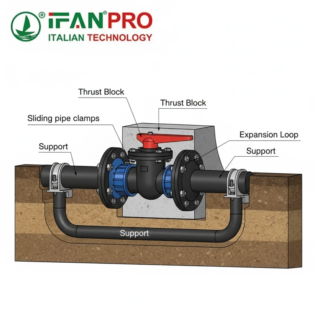
Support the pipe on both sides. Use pipe clamps or cradles that allow for axial movement (sliding supports) to accommodate thermal expansion. Place supports close to the flanged adapters, but not so close that they prevent the adapter from being installed. The goal is to let the pipe rest on the supports, not hang from the valve.
For thrust forces, when the valve is closed, water pressure creates a strong pushing force on the closed valve disc. You must restrain the pipeline on both sides of the valve to prevent it from moving. This can be done with concrete thrust blocks poured around the pipe and fittings, or with mechanical restraint systems like tie-rods or locking pipe clamps anchored to a solid structure.
Achieving Precise Alignment
Misalignment puts a bending load on the flanges and bolts, guaranteeing a leak.
Align before you fuse. After cutting the pipe, temporarily hold the valve and adapters in place with clamps or straps. Use a level and measuring tape to ensure everything is straight and at the correct height. The valve’s flange faces must be parallel to each other. Only when everything is perfectly aligned should you proceed with the final fusion of the second adapter. The first fused adapter can be used as a fixed point for alignment.
Managing Thermal Expansion
HDPE expands and contracts a lot with temperature changes. A rigidly anchored valve can get crushed or pulled apart.
Incorporate flexibility. Design an expansion loop (a U-shape in the pipe) near the valve, or use an expansion joint. This gives the pipe room to move without pushing or pulling on the valve. Supports near the valve should guide the pipe but not lock it in place axially.
Support Strategy Checklist
| Support Type | Function | When to Use |
|---|---|---|
| Sliding Pipe Clamp | Supports weight, allows pipe to slide for expansion. | Under the pipe, near (but not on) the valve adapters. |
| Concrete Thrust Block | Absorts hydraulic thrust forces from pressure. | Behind flanged fittings and valves, in buried installations. |
| Guide Clamp | Prevents lateral movement, allows axial movement. | To keep the pipe in alignment before/after the valve. |
| Expansion Loop | Absorbs thermal expansion/contraction length. | In long, straight runs where temperature varies. |
Remember: A well-supported and aligned valve installation is a permanent one. This upfront effort prevents callbacks and costly repairs.
How to Commission and Pressure Test a Newly Integrated HDPE Valve Section?
Skipping the pressure test is like buying a car without a test drive. It must be done to confirm integrity.
To commission and test, first visually inspect all joints and supports. Then, slowly fill the section with water, venting all air. Apply a hydrostatic test pressure (typically 1.5 times the system’s working pressure) for a stabilization period, then hold it for a specified time (e.g., 1 hour) while checking for pressure drops and inspecting every joint and the valve itself for leaks.
Pre-Test Inspection and Preparation
Before you put any pressure on the system, do a thorough check. Look at the fusion joints. They should have a consistent bead shape. Check the flange bolts to see if they are all present and tight. Verify that all pipe supports and thrust blocks are in place and secure. Make sure the valve is in the partially open position to allow water to fill the test section.
Next, isolate the test section. Close any valves that separate the new section from the rest of the network. Install blind flanges or test caps if needed. Connect a water fill line and a high-pressure pump with a calibrated pressure gauge. Install a vent valve at the highest point of the section to release trapped air, which is crucial for an accurate test.
Conducting the Hydrostatic Test
The formal pressure test has clear phases.
Filling and Venting: Start filling the section slowly with water. Open the vent valve at the high point. Let water flow until a steady stream comes out of the vent, indicating all air is gone. Then, close the vent valve. This step is critical because air compresses and will give false pressure readings.
Pressurization and Stabilization: Gradually increase the pressure with the pump to the test pressure. Common practice is 1.5 x the Maximum Operating Pressure (MOP). Once at test pressure, stop the pump. The pressure will likely drop slightly at first as the HDPE pipe undergoes initial “expansion and relaxation.” Allow a stabilization period (e.g., 30 minutes to 2 hours depending on standards) for the temperature and pressure to settle.
The Test Hold: After stabilization, this is the official test period. Isolate the test section from the pump. Record the starting pressure and temperature. Monitor it closely for the required hold time (often 1 hour). A small pressure drop due to minor temperature change is normal. The test is typically passed if the pressure drop is within limits specified by the project standard (e.g., no more than a 0.69 bar / 10 psi drop corrected for temperature).
Post-Test Procedures and Commissioning
While under pressure, physically inspect every part. Walk the entire test section. Look for any water weeping at fusion beads, flange gaskets, or the valve stem. Check for any movement in the supports.
If the test passes, slowly release the pressure back to zero. Open the drain valves carefully. You can now place the valve into its normal operational position (usually fully open unless needed for control).
Finally, document everything. Record the test pressure, hold time, final pressure, temperature, and any observations. This report is valuable for quality records and future maintenance.
Pressure Test Parameters Table
| Parameter | Typical Value / Action | Purpose |
|---|---|---|
| Test Pressure | 1.5 x Maximum Operating Pressure (MOP) | Verifies strength and leak-tightness under extreme conditions. |
| Stabilization Time | 30 min – 2 hours | Allows pipe material to adjust to the pressure and temperature. |
| Test Hold Time | 60 minutes | Standard observation period to detect leaks. |
| Allowable Pressure Drop | As per standard (e.g., ≤ 0.69 bar / 10 psi) | Defines the pass/fail criteria for the test. |
| Inspection | Visual check of ALL joints under pressure. | Finds leaks that might not cause a rapid pressure drop. |
Заключение
A successful HDPE valve integration requires careful planning, precise execution, and rigorous testing. For reliable HDPE valves, flanged adapters, and expert technical support, trust ИФАН for your next pipeline project.


Последние комментарии