
I once saw a pump burn out because someone ignored the pressure drop from a few simple elbows. That costly mistake taught me that every fitting counts in a fluid system.
You can calculate the pressure drop across a brass pipe elbow by using the Equivalent Length Method or the K-factor (Resistance Coefficient) Method. The simplest way is to treat the elbow as an added length of straight pipe that causes the same friction loss, then use standard flow equations to find the pressure drop based on your system’s flow rate and pipe size.
While the math is straightforward, getting accurate results depends on using the right coefficients and understanding when this calculation truly matters. Let’s break it down step by step.
What is the Equivalent Length of Pipe for a Standard 90-Degree Brass Elbow?
Engineers hate guesswork. A common error is assuming all elbows are the same, but their “cost” in pressure loss can vary widely.
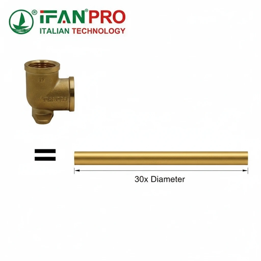
The equivalent length for a standard 90-degree threaded brass elbow is typically 30 pipe diameters. This means a 1-inch elbow adds the same friction loss as 30 inches (2.5 feet) of straight 1-inch pipe. For a flanged or sweated elbow, the equivalent length can be lower, often around 20 diameters.
Understanding the “Equivalent Length” Concept
The idea behind equivalent length is to simplify calculations. Instead of creating complex formulas for every bend and fitting, we convert their resistance into an imaginary stretch of straight pipe. This way, you only need one formula—the one for straight pipe friction—to calculate the total loss for the entire pipeline, including all its fittings.
So, if you have ten 90-degree elbows in your system, you don’t calculate each one separately. You just add up their total equivalent length to your straight pipe length.
How to Find and Apply the Value
You can find standard equivalent lengths in engineering handbooks, piping design guides, or from reputable component suppliers. The value changes based on two main things:
- The Fitting Type: A sharp, threaded elbow causes more turbulence and resistance than a smooth, long-radius bend.
- The Pipe Diameter: The rule is based on diameters, not a fixed length. This makes it scalable.
Here is a practical example:
You have a 1-inch nominal diameter brass pipe system with 4 standard threaded elbows.
- Equivalent length per elbow = 30 pipe diameters.
- 1-inch pipe has an internal diameter of about 1.05 inches.
- Equivalent length for one elbow = 30 * 1.05 inches = 31.5 inches (or 2.62 feet).
- Total added length for 4 elbows = 4 * 2.62 ft = 10.5 feet.
You would then add 10.5 feet to your total straight pipe run before calculating the overall system pressure drop. The table below gives common equivalent lengths for brass fittings.
Common Equivalent Lengths for Brass Fittings (in Pipe Diameters)
| Fitting Type | Equivalent Length (Pipe Diameters) | Notes |
|---|---|---|
| 90° Standard Threaded Elbow | 30 | Most common value for basic calculations. |
| 90° Long Radius Elbow | 20 | Smoother bend, less pressure loss. |
| 45° Standard Elbow | 16 | Less severe turn, less resistance. |
| Tee (Straight Through Flow) | 20 | For flow along the run. |
| Tee (Branch Flow) | 60 | Significant restriction for flow turning 90°. |
| Gate Valve (Fully Open) | 13 | Comparatively low resistance. |
| Globe Valve (Fully Open) | 340 | Very high resistance—this is a major source of pressure drop. |
Remember, using the correct equivalent length is the first step to an accurate calculation.
How Do Factors Like Flow Rate and Elbow Radius Affect Pressure Loss?
Pressure drop isn’t a fixed number. It changes dramatically with your system’s operating conditions and the components you choose.
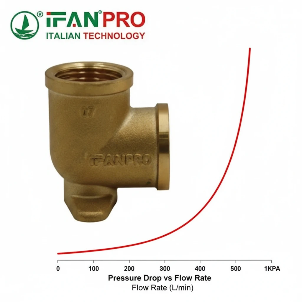
Flow rate affects pressure loss exponentially. Doubling the flow rate typically increases the pressure drop by a factor of about 4. The elbow radius has a direct linear impact; a long-radius elbow (gentle bend) can have 30-50% less pressure loss than a short-radius (sharp) elbow of the same size.
The Major Player: Flow Rate (Velocity)
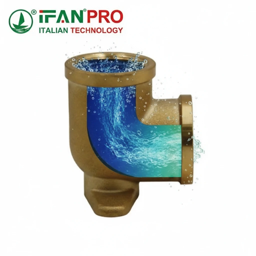
This is the most critical factor. The pressure drop in a pipe or fitting is primarily caused by friction between the fluid and the pipe wall, and by turbulent eddies created in fittings. These effects increase sharply with speed.
The relationship is governed by the Darcy-Weisbach equation. For turbulent flow (common in most water systems), the pressure drop is approximately proportional to the square of the flow velocity. This is why flow rate has such a huge impact:
- Low Flow: Low velocity, minimal friction, small pressure drop.
- High Flow: High velocity, high friction and turbulence, very large pressure drop.
Practical Implication: If your system runs at a higher flow rate than designed, the pressure drop can skyrocket, leaving insufficient pressure at the end of the line.
The Geometry Factor: Elbow Radius
The radius of the bend dictates how abruptly the fluid has to change direction.
- Short-Radius Elbow (R=1D): The bend is tight. The fluid smashes into the outer wall, creating a large zone of turbulent, slow-moving flow. This causes high energy loss. Think of taking a sharp corner at speed in your car—you have to brake hard.
- Long-Radius Elbow (R=1.5D or more): The bend is gradual. The fluid stream can follow the curve more smoothly, with less turbulence and separation. This causes significantly lower energy loss. Think of a gentle highway on-ramp.
How These Factors Work Together: A Calculation Scenario
Let’s compare two scenarios for a 1-inch brass pipe system to see the combined effect.
| Scenario | Flow Rate (GPM) | Elbow Type | Equivalent Length per Elbow | Relative Pressure Drop |
|---|---|---|---|---|
| A: Low Flow, Optimized | 5 GPM | Long-Radius (20D) | ~1.75 ft | Baseline = 1.0x |
| B: High Flow, Standard | 10 GPM | Standard Threaded (30D) | ~2.62 ft | Approx. 6x Higher |
Explanation of Result: In Scenario B, the flow rate doubled (which alone would cause a ~4x increase in pressure drop), and a less efficient fitting was used (adding ~50% more resistance). The effects multiply, leading to a pressure drop roughly six times greater than in Scenario A. This shows why both factors are crucial for design.
Where Can You Find Standard Pressure Drop Coefficients for Brass Fittings?
Good data is the foundation of good engineering. Relying on a random internet number can lead to system failure.
You can find reliable pressure drop coefficients (K-factors) or equivalent lengths in authoritative engineering references. Key sources include the Crane Technical Paper No. 410, the Hydraulic Institute (HI) Standards, engineering textbooks on fluid mechanics, and the technical datasheets provided by reputable fitting manufacturers like IFAN.

Primary Source: The Crane TP-410
For over 80 years, Crane Technical Paper No. 410 (Flow of Fluids Through Valves, Fittings, and Pipe) has been the industry’s go-to manual. It contains exhaustive tables of K-factors and equivalent lengths for virtually every type of fitting, including brass elbows, tees, and valves, across different sizes and flow conditions. It is considered the gold standard.
Other Trusted References
- Hydraulic Institute (HI) Standards: Essential for pump and pumping system design, with relevant data on system losses.
- ASHRAE Fundamentals Handbook: Contains extensive fluid flow data used in HVAC system design, applicable to water systems.
- Textbooks: Standard university texts on fluid mechanics provide the foundational formulas and typical coefficient values.
The Critical Role of Manufacturer Data
While generic standards are a great start, the most accurate data comes from the manufacturer of the specific fittings you are using. Two fittings that look identical can have different internal geometries, surface finishes, and manufacturing tolerances, all of which affect the K-factor.
A responsible manufacturer provides this data. For example, at IFAN, our technical specifications for brass fittings include certified flow resistance coefficients. This allows you to move from a safe generic estimate to a precise, optimized system calculation.
How to Use the K-Factor
The K-factor is used directly in the formula: ΔP = K * (ρ * v² / 2)
Where:
- ΔP = Pressure drop (in Pascals or psi)
- K = Resistance coefficient (dimensionless)
- ρ = Fluid density
- v = Flow velocity
A table of common K-factors offers a quick comparison:
| Fitting Description | Typical K-factor (Turbulent Flow) |
|---|---|
| 90° Standard Threaded Brass Elbow | 0.9 – 1.0 |
| 90° Long Radius Brass Elbow | 0.6 – 0.7 |
| 45° Standard Brass Elbow | 0.4 – 0.5 |
| Fully Open Brass Gate Valve | 0.2 – 0.3 |
| Fully Open Brass Globe Valve | 8.0 – 10.0 |
Always cross-reference your source and note the conditions (like Reynolds Number) for which the K-factor is valid.
When is Calculating Pressure Drop Critical for System Pump Sizing?
This calculation stops being an academic exercise and becomes a financial and operational necessity in key scenarios.
Calculating pressure drop is absolutely critical for pump sizing when designing new systems, modifying existing lines with added fittings, or troubleshooting systems with insufficient flow or pressure. It ensures the selected pump has enough total dynamic head (TDH) to overcome all friction losses and deliver the required flow at the discharge point.
Consequences of Getting It Wrong
An undersized pump (due to underestimating pressure drop) will fail to deliver the needed flow. An oversized pump (due to overestimating or ignoring losses) wastes capital cost, consumes excessive energy, and can cause control problems like cavitation and premature wear. Here are the specific situations where detailed calculation is non-negotiable:
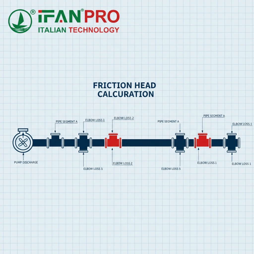
1. New System Design: This is the most obvious case. The Total Dynamic Head (TDH) for the pump is the sum of:
* Static Head: The physical height difference the fluid must be lifted.
* Pressure Head: Any required pressure at the discharge point.
* Friction Head: The total pressure drop from all pipe and fittings.
2. System Modifications or Expansions: Adding a new branch line, more equipment, or even just a few extra elbows increases the total system resistance. You must recalculate the total pressure drop to see if the existing pump can handle it or if it needs an upgrade.
3. Troubleshooting “Low Flow” or “No Pressure” Problems: Often, the pump itself is fine, but clogged pipes or an unexpectedly high number of closed valves and bends have increased the system’s pressure drop beyond the pump’s capability. Calculating the actual versus designed pressure drop helps pinpoint the issue.
A Practical Pump Sizing Checklist
To ensure you account for pressure drop correctly, follow this list when specifying a pump:
- [ ] Map the entire piping layout, counting every single elbow, tee, valve, and reducer.
- [ ] Use equivalent lengths or K-factors for each fitting to calculate total friction head.
- [ ] Add a safety factor (often 10-15%) to your calculated total head to account for uncertainties and future scaling.
- [ ] Select a pump whose performance curve meets or exceeds your required flow and calculated TDH at its best efficiency point (BEP).
Заключение
Accurately calculating pressure drop across brass elbows is essential for efficient system design. For systems built with precision, use IFAN’s engineered brass pipe fittings, which come with certified flow data for reliable calculations.


Последние комментарии