
I once received an emergency call about a valve leak on a new project site. The client was frustrated, and it cost them time and money. That moment cemented my belief in the science behind a truly leak-proof HDPE valve design.
HDPE valves ensure a leak-proof seal through a combination of robust material integrity, precision-machined components, and intelligent multi-seal mechanisms. Unlike simple threaded valves, HDPE valves, such as female threaded models, typically employ a dual-seal system where a resilient gasket works in unison with the threads to block all potential leak paths.
Let’s take a closer look at the specific engineering and installation practices that make this reliable sealing possible.
What Sealing Mechanisms Are Employed Within HDPE Female Threaded Valves?
A common mistake is to think that the threads alone are responsible for sealing. In reality, it’s a more sophisticated system.
Within HDPE female threaded valves, the primary sealing mechanisms are a soft, compressible gasket (like EPDM or NBR) seated in a dedicated groove and the precision-machined tapered (NPT) or straight (BSP) threads. The gasket provides the main fluid seal, while the tightly engaged threads provide mechanical strength and a secondary sealing barrier, especially against external ingress.
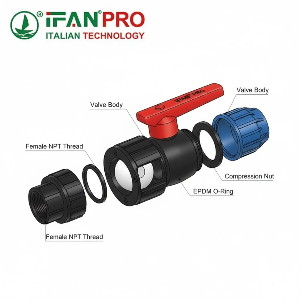
The Core Components of the Seal
A standard HDPE female threaded valve relies on a coordinated system, not just one part. The main players are the gasket and the threads. However, their roles are different, and understanding this is key to preventing leaks.
First, let’s talk about the gasket. This is usually an O-ring or a flat washer made from a material softer and more flexible than HDPE, such as EPDM rubber or Nitrile. It sits in a specially designed groove in the valve body. When you screw the male fitting into the valve, the end of the fitting compresses this gasket. This compression forces the gasket material to expand and fill any microscopic gaps between the fitting and the valve body, creating a tight, watertight seal. This gasket is responsible for sealing against the liquid pressure inside the pipe.
Second, we have the threads. HDPE valves commonly use NPT (National Pipe Tapered) threads. These threads are cut at a slight angle. As you tighten the connection, the tapered threads wedge tightly together. This creates a strong mechanical lock and significantly reduces the path for any fluid to escape. For straight threads (like BSPP), the sealing is almost entirely dependent on the compressed gasket, with the threads mainly providing the clamping force.
How These Mechanisms Work Together
The genius of this design is redundancy. It’s a two-line defense:
- Primary Seal (Gasket): Takes the main pressure load and seals the fluid.
- Secondary Seal (Threads): Provides structural stability and helps seal against external contaminants or minor pressure fluctuations.
If the gasket were to ever degrade slightly over many years, the tightly engaged threads can often maintain a sufficient seal for low-pressure applications, giving you time to identify and schedule maintenance. This is a critical safety feature in underground or hard-to-access installations.
Common Gasket Materials and Their Properties
Choosing the right gasket material is crucial for chemical compatibility and temperature resistance. Here is a comparison:
| Gasket Material | Best For | Temperature Range | Key Property |
|---|---|---|---|
| EPDM Rubber | Potable water, mild acids/bases, steam | -40°C to 120°C | Excellent weather and ozone resistance |
| Nitrile (NBR) | Fuels, oils, hydrocarbons | -30°C to 100°C | Superior resistance to oils and greases |
| Viton (FKM) | Aggressive chemicals, acids, solvents | -20°C to 200°C | Exceptional chemical and high-temp resistance |
| Silicone | High/low temperature food applications | -55°C to 225°C | Wide temperature range, flexible |
For most standard water and drainage applications, EPDM is the preferred and most cost-effective choice. At IFAN, our valves come with certified EPDM gaskets as standard, ensuring long-term reliability for common uses.
How Does the Combination of Gasket and Thread Create a Dual Seal in HDPE Valves?
Relying on a single seal is risky. The dual-seal system is what sets quality valves apart from cheap fittings.
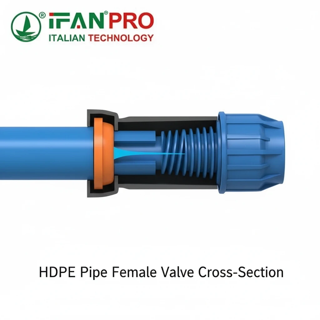
The gasket and thread create a dual seal through sequential action: first, the tightening threads pull the mating surfaces together, compressing the soft gasket to form the primary pressure seal. Then, the fully engaged tapered threads themselves mesh tightly, creating a mechanical labyrinth that blocks any potential leak path the gasket might have missed, ensuring integrity from both inside and outside.
The Step-by-Step Sealing Process
Imagine the installation process. It’s not just about tightening; it’s about creating two distinct barriers. Here is how it works, step by step:
Step 1: Initial Engagement and Gasket Contact.
As you start threading the pipe into the HDPE valve, the end of the pipe makes first contact with the raised face of the gasket. At this point, the threads are only loosely engaged and are not providing any sealing force.
Step 2: Compression of the Primary Seal.
As you continue to turn the pipe, the threads pull the pipe axially into the valve body. This action forces the pipe end to press firmly into the elastic gasket. The gasket deforms—it compresses and also expands outward against the groove walls and inward against the pipe. This elastic deformation fills all surface imperfections, creating the first and most critical seal against the system’s internal pressure.
Step 3: Engagement of the Secondary Seal.
Continued tightening causes the tapered threads to wedge together more deeply. The metal (or plastic) of the male threads makes strong, widespread contact with the female threads in the HDPE valve body. This contact creates a long, tortuous path for any fluid. For a leak to occur, it would have to travel all the way around this spiral interface, which is effectively blocked by the metal-to-plastic contact and any thread sealant (like Teflon tape) used.
The Synergy Between the Two Seals
This system is synergistic. The gasket handles the fluid dynamics—it’s designed to absorb pressure pulses and vibrations. The threads handle the mechanical dynamics—they resist forces that might try to pull the joint apart, like ground settlement or water hammer.
- The gasket compensates for small misalignments or surface scratches.
- The threads provide the immense clamping force needed to keep the gasket compressed 24/7 for years.
A failure in one does not immediately cause a total failure. A slightly worn gasket mightweep, but the threaded seal can often contain it temporarily. Conversely, if the threads were slightly under-tightened, the gasket may still hold a seal at lower pressures. This redundancy is the hallmark of a reliable design.
Common Failure Modes and How the Dual Seal Protects Against Them
Understanding failures shows why two seals are better than one.
| Potential Failure Cause | How It Affects a Single-Seal Valve | How the Dual-Seal Valve (Gasket + Thread) Mitigates Risk |
|---|---|---|
| Gasket Material Aging | Direct leak path develops as gasket hardens or shrinks. | Threads maintain a partial seal, significantly slowing leakage and allowing for planned maintenance. |
| System Vibration/Pulsation | Can loosen a threaded-only connection or fatigue a gasket. | The clamped gasket absorbs vibration, and the locked threads resist loosening. |
| Thermal Cycling | Expansion/contraction can break the seal if only one material is involved. | The elastic gasket accommodates differential movement, and threads keep components bound. |
| Improper Installation (Overtightening) | Can strip threads, causing immediate and total failure. | The gasket reaches full compression first, giving tactile feedback; stripping threads requires exceeding this point significantly. |
This dual-seal philosophy is central to the design of IFAN’s HDPE valve range. We engineer both the gasket groove dimensions and the thread tolerances to work in perfect harmony, ensuring that even under field installation conditions, a robust seal is achieved.
What Installation Torque Is Required to Achieve a Reliable Seal with HDPE Valves?
Too loose, it leaks. Too tight, it breaks. Finding the “sweet spot” is the installer’s key task.
The required installation torque for HDPE valves is not a single universal value but depends on valve size, thread type (NPT/BSP), and gasket material. Generally, for NPT threads, the goal is to achieve 2-3 full turns past hand-tight until a firm resistance is felt, indicating full gasket compression. Using a torque wrench following manufacturer specs is the most reliable method to prevent under or over-tightening.
The Problem with “Gut Feel” Tightening
One of the biggest pain points we see at IFAN is leaks caused by improper tightening. Experienced plumbers might rely on feel, but HDPE and its gaskets require a more precise approach. Over-tightening is especially dangerous. It can:
- Strip the threads in the HDPE valve body, ruining it immediately.
- Over-compress and crush the gasket, destroying its elastic recovery and causing it to fail prematurely.
- Create high internal stresses in the HDPE, leading to long-term stress cracking.
Under-tightening, of course, fails to compress the gasket sufficiently, leaving a direct path for leaks.
General Torque Guidelines and the “Turn” Method
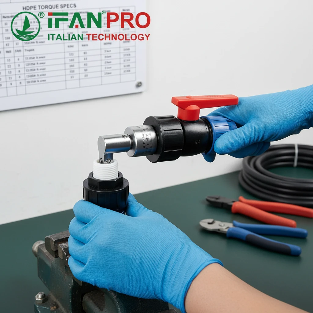
Because torque specifications require precise data from the specific valve manufacturer, a practical and commonly accepted field method for NPT threads is the “turn-of-the-nut” technique:
- Start by threading the connection by hand until it is snug (hand-tight). Ensure the threads are clean and aligned.
- Using a strap wrench or appropriate tool (avoid pipe wrenches that can crush HDPE), tighten the connection further.
- For valves and fittings between 1/2″ and 2″, the goal is typically 2 to 3 full turns past hand-tight. You will feel a significant increase in resistance as the gasket compresses fully and the tapered threads fully engage.
- Stop when this firm, consistent resistance is achieved. Do not force it further.
Recommended Torque Values for IFAN HDPE Valves
The most professional method is to use a calibrated torque wrench. The following table provides general guidelines based on common standards for NPT threads into HDPE. Always consult the specific IFAN product datasheet for the most accurate information.
| Valve Size (Inches) | Recommended Installation Torque (ft-lb) | Equivalent “Turns Past Hand-Tight” (Approx.) |
|---|---|---|
| 1/2″ | 15 – 20 ft-lb | 2 – 2.5 turns |
| 3/4″ | 20 – 25 ft-lb | 2 – 3 turns |
| 1″ | 25 – 35 ft-lb | 2.5 – 3 turns |
| 2″ | 35 – 50 ft-lb | 3 – 4 turns |
Critical Installation Tips for a Perfect Seal
Beyond torque, these steps are non-negotiable:
- Use Thread Sealant Correctly: For tapered (NPT) threads, always wrap PTFE (Teflon) tape clockwise around the male threads (2-3 layers). Do not let tape enter the pipe bore. This lubricates the threads for even engagement and fills minor thread imperfections. For straight threads (BSPP), a sealant is not used on the threads, as the gasket does all the sealing.
- Inspect the Gasket: Before assembly, check that the gasket is present, clean, and not damaged or dry-rotted.
- Avoid Contamination: Keep threads and the gasket area free from dirt, sand, or old sealant debris.
- Use the Right Tools: Use strap wrenches or tools designed for plastic. Never use a pipe wrench directly on the HDPE valve body, as it will damage it.
Following these torque and procedure guidelines ensures that the dual-seal mechanism in your IFAN HDPE valve is activated correctly, providing a leak-proof connection for the long term.
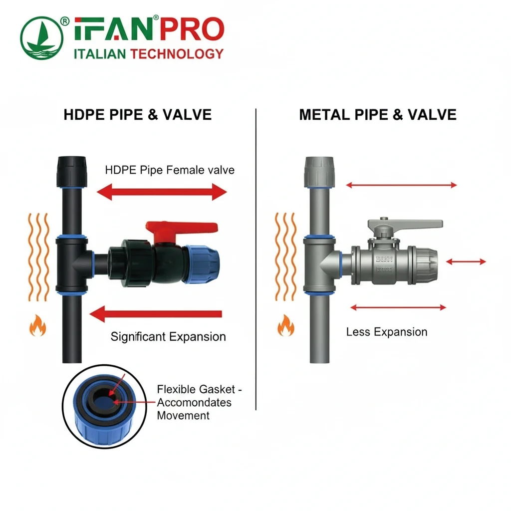
How Does Material Thermal Expansion Affect the Sealing Integrity of HDPE Valves?
Ignoring temperature changes is a recipe for joint failure. HDPE’s behavior is different from metal, and that’s a good thing.
Material thermal expansion affects HDPE valves, but their design accommodates it. HDPE has a high thermal expansion coefficient, meaning it expands and contracts more than metal pipes with temperature changes. The valve’s dual-seal system is designed to handle this: the elastic gasket absorbs the differential movement, and the long, engaged threads allow for slight dimensional change without losing grip, preventing leaks caused by stress.
Understanding HDPE’s Thermal Movement
All materials expand when heated and contract when cooled. The rate at which they do this is called the coefficient of thermal expansion (CTE). HDPE has a CTE roughly 8-10 times higher than that of steel. This means for the same temperature change, an HDPE pipe will change length significantly more than a steel pipe.
This might sound like a problem. If an HDPE valve is connected to a metal pipe and the temperature changes, wouldn’t the different rates of expansion cause the joint to break or leak? In a poorly designed system, yes. But in a well-designed HDPE valve joint, the system is ready for this.
How the Valve Design Compensates for Expansion
The dual-seal system we discussed earlier is the key to managing thermal stress.
1. The Gasket as a Stress Absorber:
The EPDM or NBR gasket is not just a static seal; it’s a flexible, resilient component. When the HDPE valve body expands or contracts relative to the connected pipe (which could be metal or another plastic), the gasket can compress slightly more or recover elastically. This flexibility allows it to maintain sealing contact even as the dimensions of the groove and the pipe end change minutely. It acts like a spring, constantly applying sealing force.
2. Thread Engagement Provides Leeway:
The long length of engaged threads provides a robust mechanical connection that can tolerate tiny axial movements without backing off. Unlike a short, shallow thread that could pop loose, the deeply engaged tapered threads in an HDPE valve maintain their grip even if the HDPE slightly changes dimension. The joint is designed to be tight and stay tight through these cycles.
Practical Implications for System Design
This characteristic has important implications for installing HDPE valve systems:
- Allow for Movement: In long, straight runs of HDPE piping, expansion loops or offsets must be designed to allow the pipe to expand and contract freely. The valve itself should not be the point where all this movement is restrained.
- Anchor and Guide Correctly: Properly anchor the pipeline near the valve to control the direction of movement. Use guides to allow axial movement but prevent lateral bending at the valve connection point.
- Consider Burial Temperature: For buried systems, the installation temperature (e.g., cool morning) versus the operating temperature (warm fluid) can be different. The system must be designed for this full range.
Comparing Thermal Expansion Impact on Different Joint Types
Not all pipe joints handle thermal stress equally.
| Joint Type | How it Handles Thermal Expansion/Contraction | Risk of Leak from Thermal Cycling |
|---|---|---|
| HDPE Valve (Gasket + Thread) | Elastic gasket absorbs movement; long threads maintain grip. | Very Low when installed correctly. |
| Soldered Copper Joint | Rigid, brittle joint; differential stress can crack solder. | Moderate to High in systems with large temp swings. |
| Threaded Metal-to-Metal | Rigid; relies entirely on thread engagement. Can loosen over cycles. | Moderate (may require re-tightening). |
| Fusion-Welded HDPE Joint | The joint becomes part of the pipe; movement is distributed. | Very Low (joint moves with the pipe). |
The takeaway is that a quality HDPE female threaded valve, like those from IFAN, is engineered not as a rigid barrier but as a flexible, adaptable link in your piping system. Its components work together to manage the natural expansion and contraction of the materials, ensuring the seal remains intact from a cold winter start-up to a hot summer operating day.
Conclusion
HDPE valves achieve reliable, leak-proof sealing through intelligent dual-seal design, correct installation torque, and built-in compensation for thermal movement. For valves that embody these engineering principles, specify IFAN’s range of HDPE Ball Valves and Check Valves for your next project.


Recent Comments