

At a client’s lab, I saw a failed experiment caused by a cheap valve’s erratic flow. This moment proved that true precision requires deliberate design.
A mini valve ensures precise flow regulation through a combination of specialized internal components, high-resolution actuation, and tight manufacturing tolerances. It is engineered to offer accurate, repeatable control over tiny fluid volumes, making it essential for applications where consistency is critical.
Let’s break down the specific engineering features that make this high level of control possible.
What Internal Design Features Enable Fine Metering in a Mini Valve?
Standard valves are too coarse for delicate tasks. The difference lies in their internal architecture.
The fine metering capability of a mini valve comes from features like a precision-machined orifice, a specially shaped plug or needle, and low-friction sealing surfaces. These elements work together to allow for very small, incremental adjustments to the flow area, giving the operator exact control over the fluid passing through.
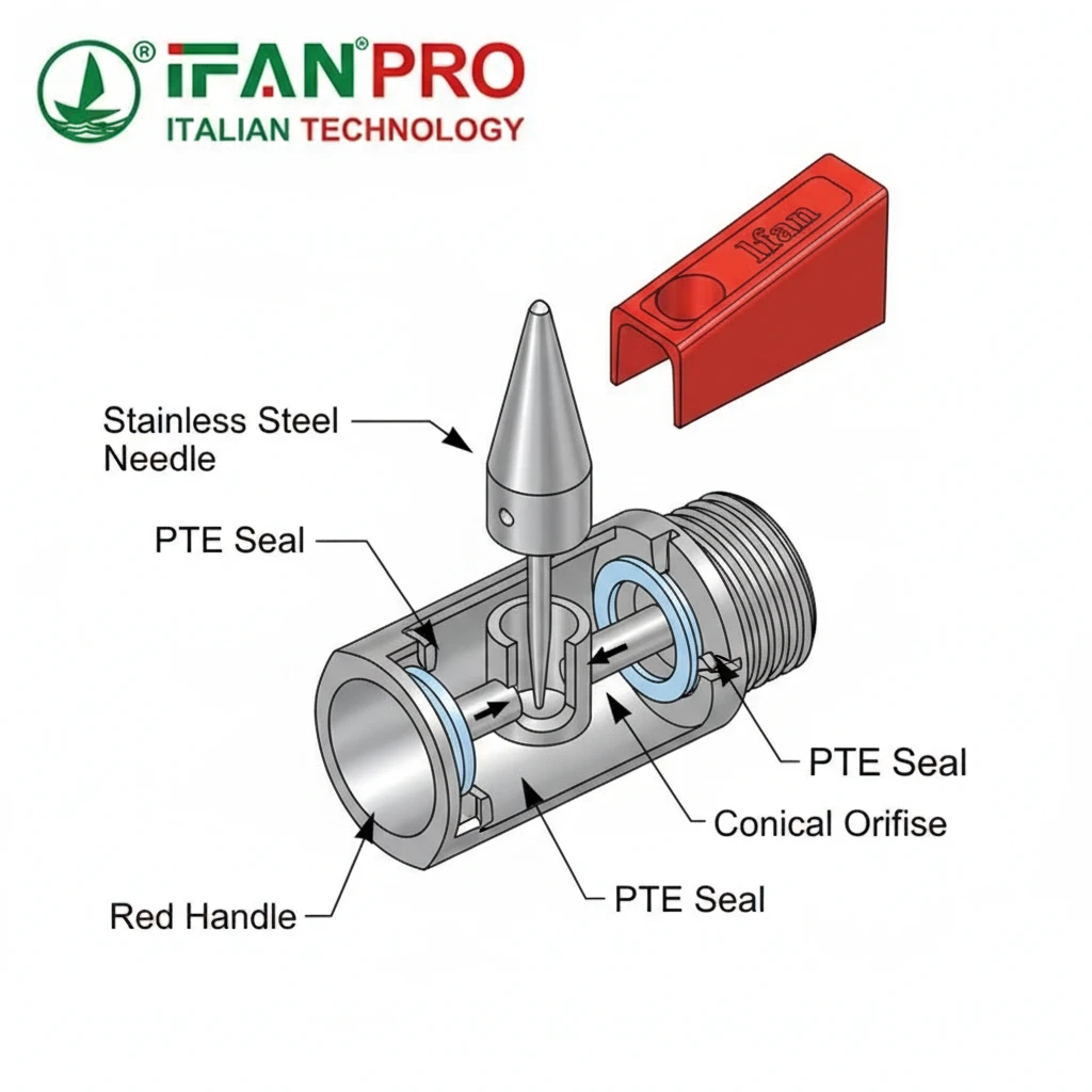
The Role of the Orifice and Plug
The heart of a metering mini valve is the relationship between its orifice and its closing mechanism. Think of the orifice as a precisely drilled hole that determines the maximum flow. The plug—often a needle with a finely tapered tip—moves in and out of this hole.
- Needle Valves: This is the most common design for fine metering. The needle’s long, gradual taper allows it to engage with the orifice over many turns of the actuator. A single full turn might change the opening by only a fraction of a millimeter. This gives you a lot of control within a small adjustment range.
- Special Plug Shapes: Some valves use plugs with parabolic or custom profiles. These shapes are engineered to create a specific relationship between the handle position and the flow rate. For example, a parabolic shape can provide a more linear flow adjustment, where turning the handle by 10% increases the flow by roughly 10%.
Importance of Low-Friction Seals and Materials
Precise control is impossible if the internal parts stick or bind. Therefore, material selection and surface finish are critical.
- Smooth Surfaces: The sealing surfaces of the plug and seat are polished to an extremely smooth finish. This minimizes friction, allowing for smooth, jerk-free adjustment. It also ensures a reliable seal when the valve is fully closed.
- Material Compatibility: The valve body, needle, and seals are chosen for their compatibility with the fluid. For instance, using PTFE seals or stainless steel bodies prevents corrosion and swelling, which could change the friction or geometry over time and ruin the metering accuracy.
Understanding Flow Path Design
A good mini valve for metering also has a simple, direct flow path. Complex internal passages can create turbulence or dead zones where fluid gets trapped. A clean, streamlined path ensures that the fluid responds immediately to adjustments and that the valve can be fully purged. Many precision mini valves use a “straight-through” design for this reason.
Comparison of Common Mini Valve Designs for Metering
| Valve Type | Primary Metering Mechanism | Best For | Key Limitation |
|---|---|---|---|
| Needle Valve | Tapered needle into a conical seat. | Precise, fine adjustment of low flow rates. | Slower to open/close fully. |
| Diaphragm Valve | A flexible diaphragm pressed against a weir. | Controlling corrosive or pure fluids without contamination. | May have a limited pressure range. |
| Ball Valve with Micro-Metering Handle | A standard ball with a geared, multi-turn actuator. | Applications needing both quick shut-off and some adjustability. | Less fine control than a true needle valve. |
| Pinch Valve | Squeezing a flexible tube to restrict flow. | Handling slurries or fluids with suspended solids. | The tube may wear out over time, affecting calibration. |
In summary, fine metering is not an accident. It results from carefully designing every internal contact point to allow smooth, predictable, and minute changes to the flow path.
How Does a Precision Actuator Achieve Accurate Positioning and Control?
The internal design is useless without an equally precise way to control it. The actuator is the interface between the user and the valve’s performance.
A precision actuator achieves accurate positioning through mechanisms like a fine-pitch threaded stem, high-resolution stepper motors, or piezoelectric elements. These components translate small control inputs into tiny, repeatable movements of the valve’s plug or needle, enabling exact and stable flow settings.
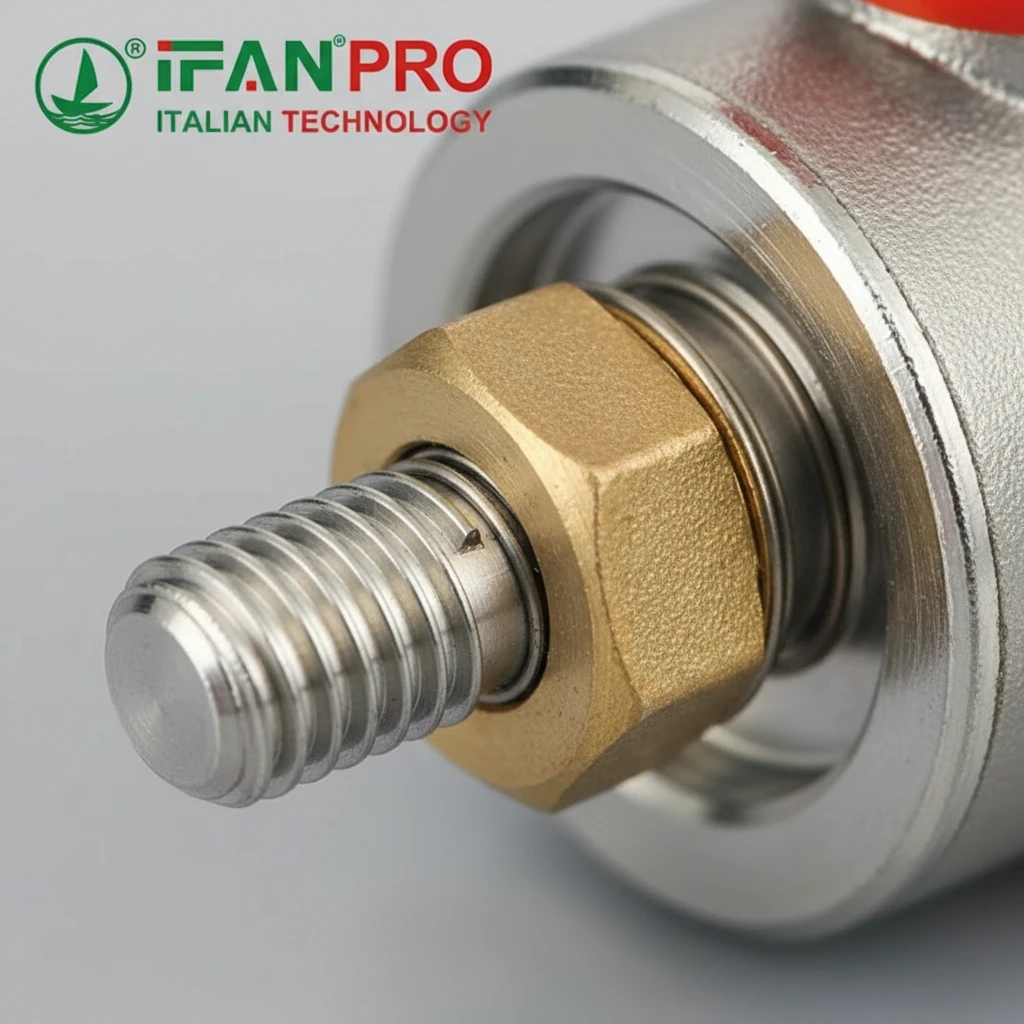
The Mechanics of Manual Precision: Fine-Pitch Threads
For manual mini valves, accuracy comes from the thread design on the valve stem.
- Thread Pitch: This is the distance the stem travels with one full turn. A fine-pitch thread (e.g., 20 turns per inch) means the stem moves only a very small amount per rotation. This gives the user a high degree of control, allowing for tiny adjustments to the flow. A coarse thread would make precise positioning difficult.
- Backlash Reduction: High-quality actuators are designed with minimal backlash or “play.” When you reverse the direction of turning, a valve with high backlash will move the handle without immediately moving the internal needle, causing imprecise control. Precision valves use special thread designs or pre-load mechanisms to eliminate this.
Automated Actuation: Stepper Motors and Piezo Drives
For automated systems, the actuator technology defines the limits of precision.
- Stepper Motor Actuators: These are very common. A stepper motor divides a full rotation into a large number of small, discrete steps (e.g., 200 steps per revolution). When coupled with the valve’s fine-pitch thread, each motor step results in a microscopic movement of the needle. This allows for digital, programmable control with extremely high positional resolution.
- Piezoelectric Actuators: These represent the cutting edge for the highest speed and precision. They use materials that change shape minutely when an electric voltage is applied. They can position a valve element with nanometer-scale resolution and can open or close in milliseconds. They are used in the most demanding analytical or semiconductor equipment.
Integrating Feedback for Closed-Loop Control
The most accurate systems don’t just command the valve to move; they verify its position.
- Position Sensors: Some advanced actuators include built-in sensors (like encoders or LVDTs) that constantly measure the exact position of the stem or needle. This feedback is sent to a controller.
- Closed-Loop Operation: The controller compares the measured position to the desired position. If there’s a discrepancy (due to friction, wear, or load), it automatically corrects it. This ensures the valve maintains its set point perfectly over time, regardless of changing conditions.
Actuator Performance Comparison
| Actuator Type | Control Method | Key Advantage | Typical Application |
|---|---|---|---|
| Fine-Pitch Manual Handle | Human operator | Simple, reliable, no power required. | Lab equipment, manual calibration points. |
| Solenoid | On/Off electrical signal | Very fast operation for shut-off. | Digital dosing, emergency shut-off. |
| Stepper Motor | Digital pulse signals | Excellent positioning resolution, programmable. | Automated chemical dosing, analytical instruments. |
| Piezoelectric | Applied voltage | Ultra-fast, nanometer-scale resolution. | High-speed inkjet printing, vibration control systems. |
In essence, the precision actuator is the “brain and muscle” of the valve, transforming a simple command into a perfectly executed mechanical adjustment.
What is the Response Time and Repeatability of a Typical Mini Valve?
Clients often confuse speed with precision. A fast valve that isn’t repeatable is useless for a process that needs consistency.
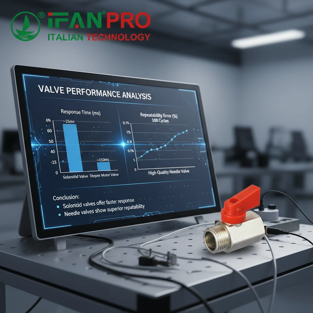
The response time of a mini valve can range from milliseconds for solenoid valves to several seconds for manually-adjusted needle valves. Repeatability, which is more critical for precision, is often within 0.5% to 1.0% of the full scale for a high-quality valve, meaning it can return to the exact same flow rate setting again and again.
Defining the Key Metrics: Response Time vs. Repeatability
It’s vital to understand these two different performance indicators.
- Response Time: This is a measure of speed. It’s the time it takes for the valve to go from one commanded state to another (e.g., from 10% open to 90% open). A fast response time is crucial for applications that need quick dosing or rapid system shutdown.
- Repeatability: This is a measure of consistency and precision. It answers the question: “If I command the valve to go to a specific position multiple times, will the resulting flow rate be the same every time?” High repeatability is essential for any calibrated process, like mixing reagents or filling containers.
Factors Affecting Response Time
Several design elements determine how fast a valve can act.
- Actuator Type: This is the biggest factor. A direct-acting solenoid is the fastest (5-100 milliseconds). A stepper motor is slower but more precise (100ms to a few seconds). A manual valve is the slowest, depending on the operator.
- Mass of Moving Parts: Lighter internal components (like a small needle) can accelerate and decelerate faster than heavy ones.
- Spring Force: In solenoid valves, a stronger spring will return the valve to its resting position faster.
Factors Critical for High Repeatability
Repeatability depends on the absence of slip, stick, and wear.
- Minimized Hysteresis: Hysteresis is the “lag” or difference in output when the input is approached from different directions. High-quality valves are designed to reduce internal friction and backlash, which are the main causes of hysteresis. Low hysteresis means the flow at 50% open is the same whether you approached it from 40% or 60%.
- Stable Sealing Materials: Seals that swell, compress, or wear over time will change the valve’s internal geometry. Using dimensionally stable materials like PTFE or specially treated metals ensures the performance today is the same as performance tomorrow.
- Robust Actuator Feedback: As mentioned earlier, closed-loop systems with position sensors offer the highest possible repeatability because they can actively correct for any deviation.
Typical Performance Ranges for Mini Valves
| Valve & Actuator Type | Typical Response Time | Expected Repeatability | Main Influencing Factor |
|---|---|---|---|
| Solenoid Valve (On/Off) | 10 – 100 ms | Not Applicable (binary operation) | Spring force, coil power. |
| Needle Valve (Manual) | 1 – 10 seconds (operator-dependent) | ±0.5% to ±2.0% of full scale | Thread wear, operator skill, hysteresis. |
| Needle Valve with Stepper Motor | 0.5 – 5 seconds | ±0.25% to ±1.0% of full scale | Step resolution, mechanical backlash. |
| High-Speed Piezo Valve | 1 – 10 milliseconds | ±0.1% or better | Drive electronics, position sensor quality. |
For most precision applications, repeatability is the more important specification. A process can often tolerate a slightly slower valve, but it cannot tolerate inconsistent results. When selecting a valve, always prioritize a strong repeatability spec over a fast response time unless speed is explicitly required.
How Do Mini Valves Maintain Stable Flow at Very Low Rates?
Achieving a low flow is one thing; keeping it steady is the real challenge. Instability at low flow can ruin sensitive processes.
Mini valves maintain stable flow at low rates by using designs that minimize internal turbulence and “dead volume,” and by employing sealing technologies that prevent unpredictable sticking or “seizing.” Features like parabolic needle profiles and hardened stainless steel seats help provide smooth, predictable control even when the valve is barely open.
The Challenge of the “Cracking” Point and Turbulence
The most difficult part of low-flow control is the initial opening and the very first percentage of travel.
- The Cracking Point: This is the moment the valve plug first lifts off its seat to allow flow. In a poorly designed valve, this point can be sudden and unpredictable, causing an initial flow “jump.” Precision valves are machined to have an exceptionally smooth seat and plug contact, allowing flow to begin in a very gradual, controlled manner.
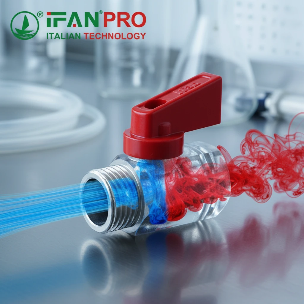
- Laminar vs. Turbulent Flow: At low flow rates, fluid should ideally move in smooth, parallel layers (laminar flow). A valve with a sharp-edged orifice or sudden changes in direction can create turbulence—chaotic, swirling motion. Turbulence causes fluctuations in pressure and flow. A well-designed mini valve has a flow path that encourages laminar flow at low settings.
Design Strategies for Low-Flow Stability
Manufacturers use specific design approaches to conquer low-flow instability.
- Special Needle Profiles: A standard tapered needle might provide good control in the mid-range but poor control at the very tip. A parabolic or characterized needle profile is shaped to give a more linear and stable flow increase right from the beginning of opening.
- Elimination of Dead Volume: Dead volume is any space in the valve where fluid can become trapped and stagnant. This stagnant fluid doesn’t move with the main flow and can cause pulsations or delays. Precision low-flow valves are designed with a compact internal volume and a flow path that sweeps fluid through completely.
- Hardened Materials for the Seat: At very low openings, the needle tip is exerting high pressure on a very small area of the seat. If the seat material is soft, it can deform over time, changing the flow characteristics. Using a hardened stainless steel seat or a ceramic seat prevents this deformation, ensuring long-term stability.
Dealing with External Factors
The valve itself must also be resilient to system changes.
- Pressure Independence: A good low-flow valve should maintain a set flow rate even if the upstream or downstream pressure changes slightly. This is often achieved by using a design that creates a high pressure drop across the valve orifice, making the flow less sensitive to variations in the rest of the system.
- Temperature Compensation: Extreme temperature changes can cause metal parts to expand or contract. Valves designed for critical applications may use materials with similar thermal expansion coefficients for the body and the needle to maintain clearances and performance across a wide temperature range.
Guide to Selecting a Valve for Low Flow Applications
| Application Requirement | Recommended Valve Feature | Reason |
|---|---|---|
| Extremely Low Flow (Droplets per minute) | Needle valve with a characterized (parabolic) tip. | Provides smooth, controllable flow right from the cracking point. |
| Stability with Varying System Pressure | Valve designed for a high pressure drop. | Makes the flow rate less sensitive to pressure fluctuations upstream/downstream. |
| Handling Viscous Fluids | Larger orifice size relative to flow, straight-through flow path. | Reduces the chance of clogging and minimizes required opening force. |
| Long-Term Calibration Stability | Hardened (e.g., stainless steel) seat and stem. | Prevents wear and deformation at the critical sealing point, preserving accuracy. |
In summary, stable low-flow performance is a hallmark of a well-engineered mini valve. It requires attention to microscopic geometry, material science, and fluid dynamics to ensure that when you set a tiny flow, it stays exactly as set.
Conclusion
Precise flow regulation depends on thoughtful internal design, accurate actuation, reliable repeatability, and stable low-flow control. For your most demanding applications, specify IFAN’s precision miniature needle valves for guaranteed performance.


Commentaires récents