
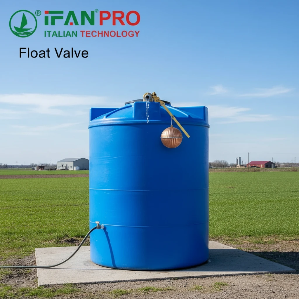
I once had a client whose water tank overflowed constantly, wasting water and money. The problem was a cheap, failed float valve. This experience cemented my belief in understanding how these essential devices truly work.
A float valve controls water level automatically through a simple mechanical principle: a floating ball attached to a lever arm rises and falls with the water level. This movement directly opens or closes the water inlet, maintaining a consistent pre-set level without any need for electricity or manual intervention.
It’s a brilliant and reliable system. Let’s dive into the mechanics behind this everyday marvel and see how each part plays its role.
What is the Basic Mechanical Principle Behind a Float Valve Operation?
The best designs are often the simplest. A float valve’s genius lies in using fundamental physics to solve a practical problem.
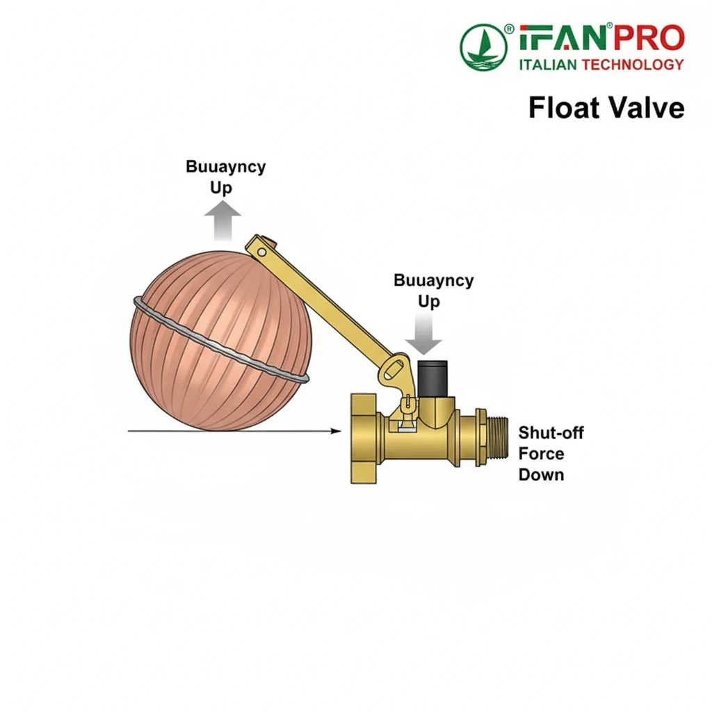
The basic mechanical principle is buoyancy and lever action. A hollow, buoyant float ball rests on the water’s surface. As the water level rises, the ball rises with it. The ball is connected to a lever arm, which pivots. This pivoting arm is connected directly to a valve plug, transforming vertical float movement into a horizontal shut-off action.
The Core Idea: A Physical Feedback Loop
To understand float valves, think of a simple feedback loop. The system senses the water level, compares it to a desired level, and makes a correction. All of this happens through physical parts moving in response to water.
The key elements in this loop are the Float, the Lever Arm, and the Valve Seat. The float is the sensor. It’s usually a hollow plastic or copper ball that floats because it’s filled with air. Its only job is to follow the water surface up and down.
How the Lever Amplifies Force
The lever arm is the decision-maker and the muscle. It’s a simple metal or plastic rod that pivots on a fulcrum (a pin or hinge). The float is attached to one end. The other end is connected to the valve’s sealing plug or piston.
This lever system does two important things. First, it changes the direction of force. The float moves up and down, but the valve plug needs to move side-to-side to seal against an inlet. The lever pivots to make this direction change happen.
Second, it provides mechanical advantage. You don’t need a giant float to close a valve against strong water pressure. The lever arm design multiplies the force from the buoyant float, allowing a relatively small, light ball to control a powerful water stream.
A Simple Comparison to Understand
It works much like the old-fashioned toilet tank mechanism. When you flush, the water level drops, the float ball falls, and the lever arm opens the fill valve. Water comes in, the float rises, and the lever slowly shuts the valve off. A float valve in an industrial tank or animal waterer operates on the exact same principle, just often on a larger, more robust scale.
| System Part | Its Role in the Principle | Real-World Analogy |
|---|---|---|
| Float Ball | The sensor. Rises/Falls with water level. | A person watching a bathtub fill up. |
| Lever Arm | The controller & amplifier. Converts motion and applies force. | Your arm that reaches to turn the tap on/off. |
| Valve Seat | The actuator. The part that physically stops the flow. | The rubber stopper you press onto the bathtub drain. |
This principle makes float valves incredibly reliable and self-contained. They fail only when a physical part breaks, wears out, or gets stuck—issues we can usually prevent or fix easily.
How Does the Rising Float Physically Shut Off the Water Inlet Valve?
Seeing a tiny float stop a powerful jet of water is impressive. The shut-off is a precise mechanical dance, not just a simple plug.
The rising float shuts off the inlet by pulling on the lever arm, which either directly lifts a rubber plunger onto a seat or slides a piston across an orifice. This action uses the water pressure itself to aid in sealing, creating a tight, leak-proof closure that can withstand significant upstream pressure.
The Two Main Shut-Off Mechanisms
There are two common designs, but both achieve the same goal. Understanding them helps in selecting the right valve and troubleshooting.
1. The Piston/Plunger Type (Most Common):
This is the classic design. Here’s how it works step-by-step:
- The inlet water pressure pushes against a small piston or plunger inside the valve body, trying to force it open.
- This plunger is held in the open position by the lever arm when the float is down.
- As the float rises, it pulls the connected end of the lever arm up.
- Because the lever pivots, the other end (connected to the plunger) pushes down.
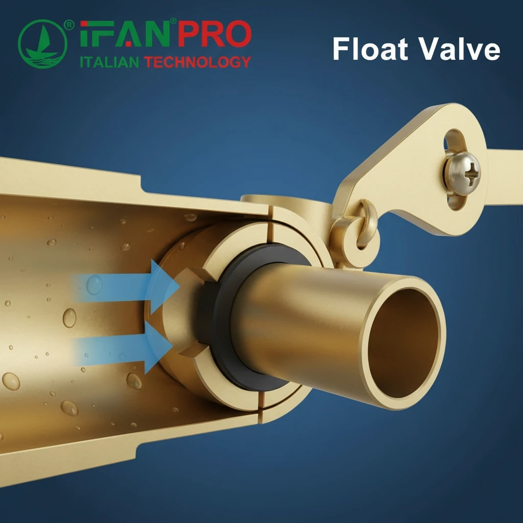
- This downward push forces a soft rubber or silicone washer on the plunger onto a precisely machined “seat” (a hole where water enters).
- Once the washer contacts the seat, the incoming water pressure itself pushes up on the bottom of the washer, squeezing it firmly against the seat. This creates a powerful, pressure-assisted seal.
2. The Diaphragm Type (For Higher Pressure):
This design is even more effective for stronger water pressure.
- It uses a flexible rubber diaphragm to control water flow.
- A small pilot hole allows water pressure to build up in a chamber above the diaphragm.
- When the float is up, the lever arm closes this pilot hole.
- With the pilot hole closed, pressure equalizes above and below the diaphragm, and a spring (or the water pressure from below) pushes the diaphragm down to seal the main inlet.
- The water pressure across the entire diaphragm area creates an exceptionally strong sealing force, allowing a small float to control very high-pressure lines.
The Critical Role of the Seal
The actual shut-off happens at the seal—typically the rubber washer or diaphragm. This component is vital. It must be flexible enough to conform perfectly to the metal seat but durable enough to resist wear and chemical breakdown from water.
A common client pain point is a slow leak or drip from the inlet even when the float is up. Nine times out of ten, the cause is a worn, hardened, or damaged seal. Grit or mineral scale on the valve seat can also gouge the soft seal and prevent a perfect closure.
| Symptom | Likely Shut-Off Problem | Simple Fix |
|---|---|---|
| Constant slight drip/flow | Worn or deformed rubber seal. | Replace the seal/washer. |
| Water spurts out, doesn’t shut off | Seal is missing, torn, or has debris on it. | Clean the valve seat & chamber; install new seal. |
| Valve chatters or vibrates loudly | Seal is partially closing/opening rapidly; often due to high pressure or a weak lever assembly. | Install a pressure-reducing valve upstream or check for a sticking float/lever. |
The beauty of the design is its use of the system’s own water pressure to achieve a secure shut-off, making it both effective and energy-efficient.
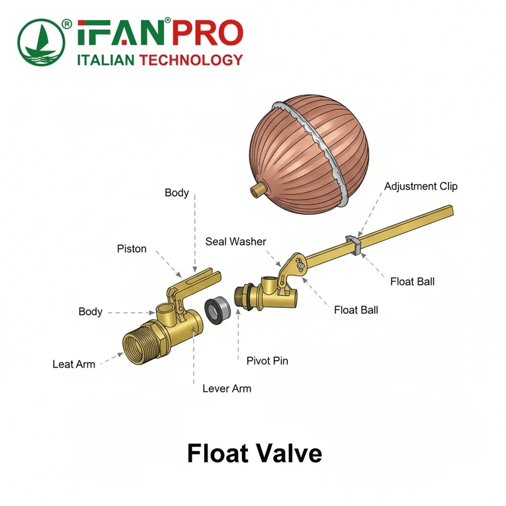
What are the Main Internal Components of a Typical Float Valve Mechanism?
Reliability comes from quality parts working together. Knowing the components turns a mysterious brass body into a logical system.
The main internal components are the float ball, the lever arm assembly (with pivot and adjustment clip), the valve body, the sealing mechanism (piston/plunger with washer or diaphragm), and the valve seat. Each part has a specific job in translating float movement into reliable water flow control.
Component Breakdown and Function
Let’s open up a typical piston-type float valve and look at each piece from the inside out.
1. The Valve Body:
This is the main housing, usually made of brass, stainless steel, or durable plastic. It has an inlet port (threaded for connection to your water supply) and an outlet port (where water enters the tank). Its internal machining is critical—it contains the water passageways and the precise valve seat that the seal presses against.
2. The Sealing Mechanism (Heart of the Valve):
- Piston/Plunger: A small, precisely moving rod inside the valve body.
- Seal Washer: A rubber or silicone ring attached to the end of the piston. This is the part that makes contact.
- Spring (often): A small spring that helps retract the piston when the lever releases it, ensuring a quick, positive opening.
3. The Lever Arm Assembly:
- Lever Arm: The metal rod that transmits force. It often has multiple adjustment holes for the float rod.
- Pivot Pin/Fulcrum: The hinge point that allows the lever to rock.
- Float Rod: The thin rod connecting the lever arm to the float ball. It is often threaded or has a clip for adjusting the water level.
- Adjustment Clip/Bend: The means to change the effective length of the float rod. Bending the rod or moving a clip changes how high the float must rise to shut the valve.
4. The Float Ball:
The buoyant sensor. It must be watertight. A leak that allows water inside will cause the valve to fail (the float will sink and water will run continuously).
How They Connect: The Flow Path
Understanding the order helps with troubleshooting. Water enters the inlet, flows into a chamber pushing against the piston. When open, water goes around the piston, past the retracted seal, out the outlet, and into the tank. The tank fills, lifting the float ball. The float rod pulls the lever arm, which pushes the piston down, jamming the seal against the valve seat. Flow stops.
Material Matters: Choosing the Right Valve
The choice of materials for each component determines the valve’s lifespan and suitability for different water types.
| Component | Common Materials & Their Purpose |
|---|---|
| Valve Body | Brass: Durable, corrosion-resistant for most potable water. Stainless Steel: For aggressive water or high-sanitation applications. Plastic (PP/Nylon): Lightweight, corrosion-proof for chemicals or fertilizers. |
| Seal Washer | Nitrile Rubber: Good general use, cost-effective. EPDM Rubber: Excellent for hot water and weathering. Silicone: Wide temperature range, very flexible, food-safe. |
| Float Ball | Copper: Durable, traditional, but can dent. Plastic (PE/PP): Lightweight, corrosion-proof, modern standard. |
| Lever Arm | Stainless Steel: Prevents rust, ensures smooth operation. Galvanized Steel: Strong but can corrode over time. |
Selecting a valve with the right materials—like the corrosion-resistant builds IFAN offers—prevents common failures like seized levers, broken plastic, or degraded seals.
How Does the Valve Reopen When the Water Level Drops During Usage?
A good valve shuts off reliably; a great one reopens just as reliably. The reopening mechanism ensures a steady water supply on demand.
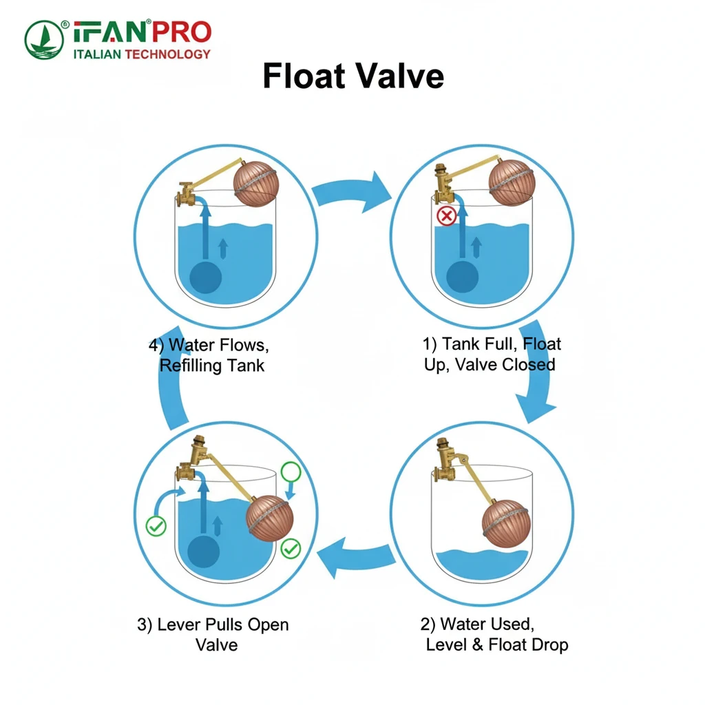
The valve reopens through the reverse process: water usage lowers the tank level, causing the float ball to descend. Its weight pulls down its end of the lever arm. The lever pivots, retracting the plunger or piston from the valve seat. This opens the inlet, and water pressure pushes the valve fully open, allowing water to flow in until the float rises and shuts it off again.
The Cycle of Use: A Step-by-Step Look
The automatic reopening is what makes the system truly “set and forget.” Here’s the full cycle:
- Demand Phase: Someone (or something) uses water from the tank—a toilet flushes, an animal drinks, or a machine draws water.
- Level Drops: The water level in the tank falls by a few centimeters or inches.
- Float Descends: The float ball, sitting on the surface, sinks down with the water level. Gravity is now the acting force.
- Lever Arm Reverses: The sinking float pulls its end of the lever arm downward. Because the lever pivots in the middle, the opposite end (connected to the valve plunger) moves upward.
- Valve Unseats: This upward motion lifts the rubber seal washer away from the metal valve seat. Even a tiny gap is enough.
- Water Pressure Takes Over: The moment the seal loses contact, the full pressure of the incoming water supply acts on the plunger or diaphragm. This hydraulic force pushes the valve mechanism to its fully open position almost instantly. Water rushes into the tank.
- Refill Phase: The incoming water flow is now much faster than the outflow from usage. The tank level begins to rise.
- Return to Set Point: The rising water lifts the float. The lever arm begins to slowly, steadily push the plunger back toward the seat, gradually restricting the flow. This prevents a sudden, water-hammer inducing slam shut.
- Shutoff (Repeat): The float reaches its pre-set height, the seal contacts the seat, and water pressure locks it closed. The system is back at rest, ready for the next use cycle.
Ensuring Smooth Reopening: Critical Factors
Several factors ensure this reopening happens smoothly every time:
- Free-Floating Mechanism: The float, lever, and plunger must move freely without sticking. Corrosion, bent parts, or debris can cause the valve to “hang up” and not open even when the float drops.
- Adequate Inlet Water Pressure: The valve relies on water pressure to snap open quickly. Very low inlet pressure can cause slow, sluggish reopening and inadequate refill rates.
- Proper Lever and Float Weight: The float must be heavy enough to reliably fall and pull the lever down. If the float is too buoyant or the lever is too stiff, it may not open until the water level drops very low.
Common Reopening Failures and Fixes
Clients often face issues where the tank doesn’t refill, or refills too slowly.
| Problem | Cause | Practical Advice |
|---|---|---|
| Tank empties, valve won’t reopen. | 1. Lever arm is bent or jammed against the tank wall. 2. Pivot pin is corroded and seized. 3. Mineral deposits have glued the plunger inside the valve body. | Ensure free movement. Lubricate the pivot pin with silicone grease. Soak the valve in vinegar to descale. |
| Tank refills very slowly. | 1. Partially clogged inlet filter or valve orifice. 2. Very low incoming water pressure. 3. Plunger is not retracting fully due to a worn spring or obstruction. | Check and clean the inlet filter/screen. Check upstream pressure. Inspect and clean the internal chamber. |
| Valve “chatters” (rapid on/off) during refill. | Water pressure is too high, causing the valve to slam shut violently and bounce open repeatedly. | The best solution is to install a pressure-reducing valve on the main supply line before the float valve. |
A well-designed float valve, like those in the IFAN range, accounts for these factors. They use corrosion-resistant materials for smooth movement, include built-in filters to prevent clogging, and are rated for a wide pressure range to ensure consistent opening and closing performance.
Conclusion
The float valve is a perfect example of smart, simple, and reliable mechanical design. For durable, high-performance float valves built with quality materials, trust IFAN to deliver automatic control you can count on.


Commentaires récents