
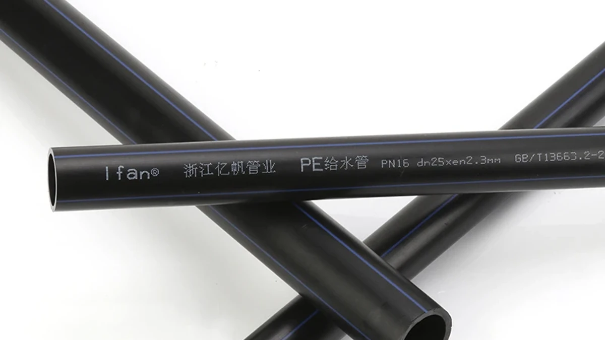
Check HDPE flotation for the construction stage that can be flooded, not only for the final buried condition. Compare displaced-fluid uplift with the pipe, its actual contents and the resistance already present. Count submerged ballast by its weight in water, not its dry weight. Filling the pipe reduces uplift; it does not by itself prove that the installation is stable.
A pipe can be satisfactory under its final cover and still move while the trench is open. The vulnerable period may be overnight rain, a pump interruption or a fluid-backfill placement. The calculation must describe that state. Soil shown on the finished drawing cannot resist uplift before it has been placed and can perform the role credited to it.
Key Takeaways
- Review the actual construction sequence as well as the final buried condition.
- Fully submerged uplift uses the pipe’s outside displaced area, not its internal bore.
- Pipe contents reduce residual uplift only when those contents are actually present.
- Submerged concrete contributes its weight minus the weight of displaced fluid.
- Fresh flowable fill needs its own placing-condition check; it is not automatically resisting soil.
- A vertical force screen does not approve ballast spacing, attachment, bearing or external-pressure buckling.
Check the stage that can actually float
The Plastics Pipe Institute’s buried-design guidance identifies shallow-cover flotation as a separate design condition. Ordinary earth-load and traffic checks do not automatically close it. In particular, a completed backfill design does not describe an empty pipe in a flooded excavation.

| Stage | Relevant uplift | Resistance that can be considered |
|---|---|---|
| Dry trench, empty pipe | No surrounding-water buoyancy in the assumed dry state | Review what happens if water returns before the next stage. |
| Flooded trench, empty uncovered pipe | Displaced water around the submerged pipe | Pipe self-weight and verified restraints; no future cover or future contents |
| Flooded trench, water-filled pipe | Same external displacement at the same water level | Add the actual contained-water weight; do not assume all uplift disappears. |
| Partially backfilled pipe | Actual water level and displaced volume | Only the soil/restraint resistance justified for that actual stage |
| Fresh flowable fill being placed | Displacement in the placing fluid | Designed temporary controls and any resistance already established |
Conceptual load cases. PPI Handbook of PE Pipe, Chapter 6, treats groundwater flotation; Armtec’s flotation bulletin separately flags flowable-fill placement. This table supplies no approved construction sequence.
Document whether the pipe is empty, partly filled or full, and whether it can drain or trap air during the stage. “We will fill it” is a proposed control, not an existing downward force. If the plan depends on that control, its maintenance and loss must be considered explicitly.
Use the actual water level too. Fully submerged and partially submerged pipe displace different volumes. A water level below the pipe invert removes this groundwater-uplift mechanism for that stated condition, but it does not demonstrate that the trench will stay dry or settle the other installation checks.
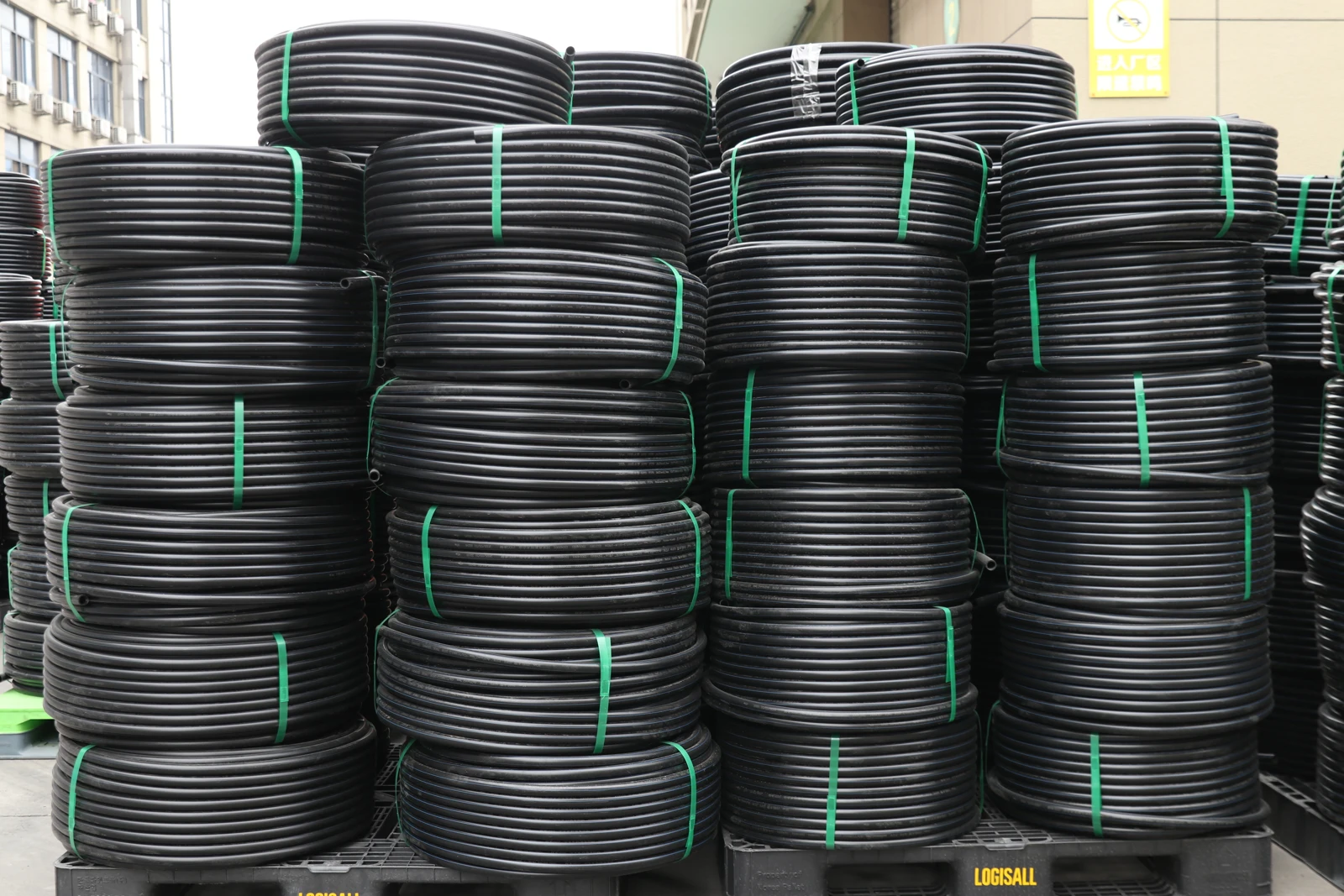
Build one consistent force balance
For a straight, fully submerged cylindrical pipe, calculate uplift per unit length from the outside area. In SI force units:
U = γf × πDo2/4, where U is uplift in kN/m, γf is surrounding-fluid unit weight in kN/m³, and Do is actual outside diameter in m. For partial submergence, replace the full circular area with the area actually submerged. The internal diameter belongs in the contents calculation, not in external displacement.
Armtec’s Pipe Flotation of BOSS HDPE Pipe gives the underlying external-displacement relationship. Its product weights and minimum-cover tables concern BOSS drainage pipe; they are not a design table for an offered solid-wall pressure pipe. The relation is useful here as physics, with the units stated explicitly.
Subtract actual pipe weight and contents weight from uplift to obtain the residual upward force before soil or ballast is credited. Use force per metre throughout. If a datasheet gives mass in kg/m, convert it to kN/m before combining it with forces. For contained liquid, use its unit weight multiplied by the area actually occupied inside the pipe.
Then treat a fully submerged concrete ballast consistently: submerged contribution = (γc − γf) × Vc. Here Vc is the actual concrete material volume associated with the reviewed length, not the outside envelope of a hollow collar. PPI’s Handbook of PE Pipe, Chapter 10, page 369 explicitly distinguishes ballast weight in water from weight in air. The marine-installation discussion supports this weight distinction; it does not prescribe buried-pipe anchor spacing.
There are two equivalent bookkeeping approaches: sum all displaced-fluid uplift and all dry weights, or use net submerged weights for the added solid ballast. Do not subtract the ballast’s buoyancy in both places. Keep the concrete, pipe and any voids in the same defined physical system.
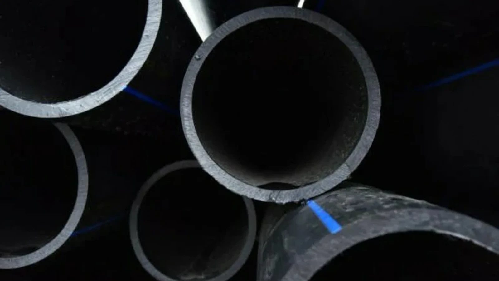
A metric example: empty pipe and submerged ballast
Teaching assumptions, not a product specification: consider a uniform, fully submerged pipe with outside diameter 0.315 m, inside diameter 0.277 m and assumed pipe mass 17 kg/m. Take freshwater unit weight as 9.81 kN/m³ and gravity as 9.81 m/s² for this example. Ignore soil, currents, design factors and restraint geometry. These invented inputs illustrate arithmetic; they identify no IFANPRO model or customer project.
- External displacement: π × 0.315²/4 = approximately 0.07793 m². Multiply by 9.81 kN/m³ to obtain U ≈ 0.765 kN/m.
- Pipe weight: 17 × 9.81/1,000 ≈ 0.167 kN/m. The empty pipe therefore has approximately 0.598 kN/m residual upward force before other resistance.
- Water-filled bore: π × 0.277²/4 ≈ 0.06026 m². Its contained-water weight is approximately 0.591 kN/m. Residual uplift is then approximately 0.0066 kN/m, still upward in this hypothetical case.
The comparison shows why filling can be powerful without proving stability. It removes most of the empty-bore contribution, but “almost balanced” is not a design margin. An incompletely filled section, changed surrounding fluid or loss of the filling control changes the result.
| Quantity | Empty pipe | Water-filled pipe |
|---|---|---|
| External water uplift | 0.765 kN/m upward | 0.765 kN/m upward |
| Pipe self-weight | 0.167 kN/m downward | 0.167 kN/m downward |
| Contents weight | Not credited | 0.591 kN/m downward |
| Residual before soil or ballast | 0.598 kN/m upward | 0.0066 kN/m upward |
Calculated from the stated teaching assumptions using unrounded intermediate values; displayed values are rounded. No safety factor or structural acceptance is represented.
| Actual bore-water fraction (0–1) | Residual upward force (kN/m) |
|---|---|
| 0 | 0.5977344124061269 |
| 0.25 | 0.44993985695258765 |
| 0.5 | 0.30214530149904845 |
| 0.75 | 0.1543507460455092 |
| 1 | 0.00655619059196999 |
Now compare ballast accounting. Additional teaching assumptions: suppose actual concrete material volume is 0.050 m³ per metre of pipe, with assumed concrete unit weight 24 kN/m³, fully submerged in the same water. Its dry weight is 24 × 0.050 = 1.200 kN/m. Its submerged contribution is (24 − 9.81) × 0.050 ≈ 0.710 kN/m. Counting the dry weight would overstate resistance by approximately 0.491 kN/m.
That 0.710 kN/m exceeds the example’s unfactored empty-pipe uplift of 0.598 kN/m. It establishes only the direction of this simplified force balance. It does not approve that concrete volume, a block shape, a spacing or the means of transferring force into the pipe. Those require an actual engineered design and its governing factors.
Choose controls for the vulnerable stage
The useful choice is between controls that can operate during the identified stage. Dewatering limits the surrounding-water condition; controlled water filling adds contents weight; suitable backfill or an engineered restraint provides resistance. Each changes a different term or condition. A plan should state which term it relies on, when that term becomes available, and what happens if it is lost.
For an uncovered pipe that could flood before the next work period, crediting the eventual soil cover is the wrong starting point. Review a temporary control for that interval. If water filling is proposed, verify the actual fill state and whether the contents can be retained. If dewatering is proposed, consider interruption and the resulting water level. If ballast or anchors are proposed, review their load transfer, local pipe effects and supporting ground as well as the net weight.
Flowable fill is a separate placing condition. The liquid mix displaces volume before it becomes a solid support. Use the actual placing-fluid properties and lift condition; do not automatically count its full eventual solid weight as immediate hold-down. Armtec flags this exposure specifically. A generic “concrete backfill prevents flotation” statement skips the stage in which the pipe can move.
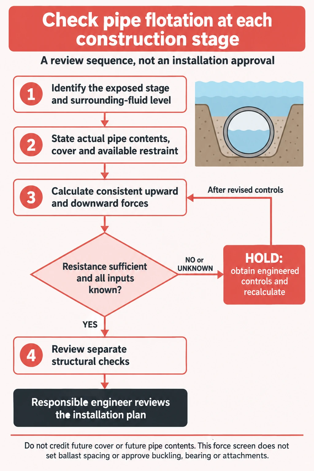
For review, retain this sequence in readable form:
- Identify the exposed stage and credible surrounding-fluid level.
- State the actual pipe contents, cover and restraint already available.
- Calculate consistent upward and downward forces for that state.
- Where resistance is insufficient or an input is missing, obtain the engineered temporary/permanent control and recalculate.
- Review the separate structural checks before accepting the installation plan.
Turn the calculation into a review decision
The example yields a clear screening disposition: the empty, fully submerged pipe needs additional verified resistance or a changed exposure condition. Water filling sharply reduces its residual uplift. The assumed concrete volume produces more net downward contribution than that unfactored residual, but cannot be released as a design from this arithmetic alone.
For an actual trench, the missing inputs are specific. Obtain the actual pipe OD and mass, contents state, credible water/fluid level and properties, actual cover geometry and soil properties, and the proposed ballast’s material volume and density. These inputs change either displacement or resistance. Apply the project’s required load/resistance or safety-factor method to the resulting forces; do not import a universal factor from another installation.
Where soil resistance is claimed, the soil model and actual stage must support that claim. Where a discrete ballast is claimed, the reviewed spacing, attachment and bearing must transfer the calculated force without unacceptable local effects. PPI also separates hydrostatic buckling from flotation: stopping upward movement does not demonstrate that the pipe wall can withstand the external-pressure condition.
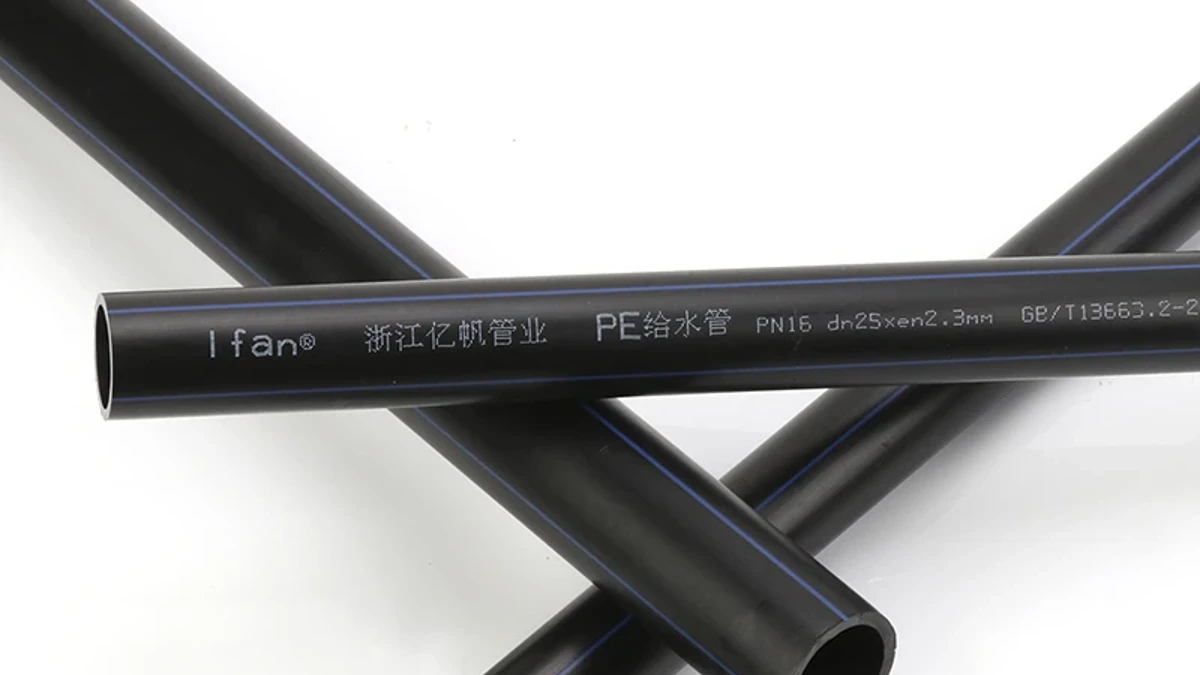
For the pipe side of that review, IFANPRO’s HDPE pipe-and-fitting category is a starting reference. It does not confirm the hypothetical dimensions or mass used above. Match a real datasheet and the required installation duty before treating a product as a candidate.
A contractor or project buyer can Check HDPE pipe and fitting availability with the required material, OD, wall series, documentation, quantities and destination. This is a conditional supply enquiry, not an offer of trench, dewatering or ballast design.
Conclusion
Check the pipe that exists at the exposed stage, with the water, contents and resistance present at that time. Use outside displacement for uplift and submerged weight for ballast. The resulting force screen reveals which condition needs control; the actual construction and structural design must then show how that control works.
Frequently Asked Questions
Does a water-filled HDPE pipe always sink?
No. Filling reduces the air-bore contribution, but the pipe, contents and surrounding fluid still need a consistent force check. The hypothetical full-pipe example retains slight upward force.
Can I use the final backfill weight during installation?
Only resistance justified for the actual stage can be credited. Future cover cannot hold down an uncovered pipe now.
Why is submerged concrete weight lower?
The concrete displaces fluid and experiences its own buoyancy. Its net contribution is its dry weight minus that displaced-fluid weight.
Does passing the force balance settle external-pressure buckling?
No. Flotation and wall buckling are separate checks. Ballast attachment, local loading and ground support also need the applicable engineering review.










 Français
 English
 Русский
 Español
Commentaires récents