
I once received a frantic call because a buried pipe elbow had shifted and caused a major leak. The problem wasn’t the pipe itself, but a weak, unsuitable seat. This experience taught me a tough lesson about the critical importance of proper base design.
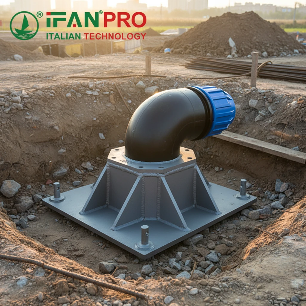
Yes, engineers can and should specifically design elbow seats for direct burial or anchoring. A generic flat plate will often fail under soil pressure and pipe thrust. Therefore, the design must actively counteract buoyant, lateral, and axial forces. Designers achieve this by incorporating features like increased surface area, integrated anchoring points, and structural reinforcement to ensure the entire pipeline remains stable for decades.
Now, let’s examine the key design features that make a buried or anchored elbow seat both reliable and long-lasting.
What Specific Seat Features Are Required for Secure Direct Burial Applications?
You cannot simply bury an elbow in dirt and expect it to stay put. The soil moves, water flows, and pressure builds, so the design must be intelligent and robust.
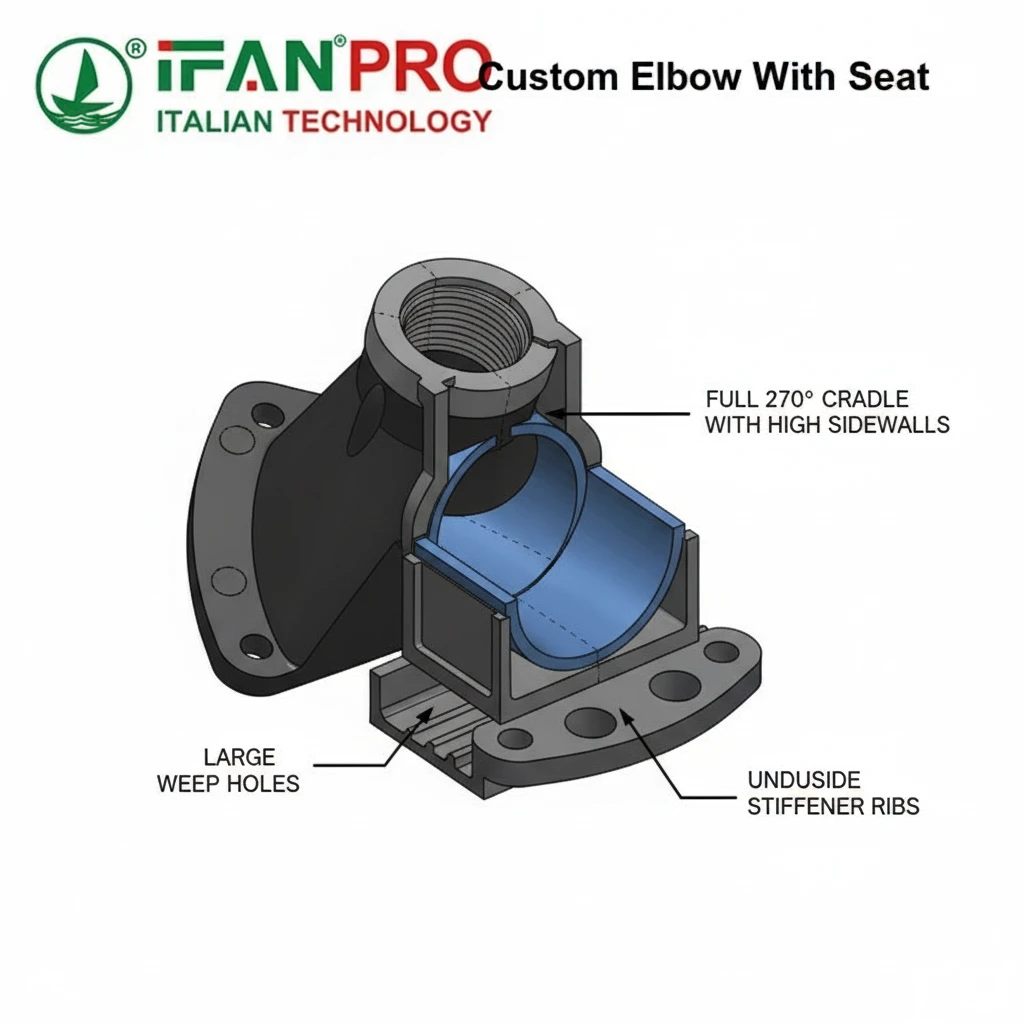
For secure direct burial, an elbow seat first needs a large, reinforced base plate to distribute the load. Secondly, it requires high sidewalls or a full cradle to prevent roll-out. Finally, it must include strategic weep holes to prevent water buildup and hydrostatic pressure underneath the structure, which could otherwise lift it.
The Core Principle: Resisting Movement
The primary function of a direct burial seat is to stop the elbow from moving. Pipe elbows are natural pressure points in any system. Essentially, the flowing water wants to push the elbow straight, which creates strong thrust forces. If the elbow moves, the connected pipes can bend, the joints can fail, and leaks will start. Consequently, a proper seat must lock the elbow firmly in place.
Essential Design Features
First, the seat must have a large bearing surface. Think of it like the foundation of a house. A small concrete pad will sink, but a large, wide one stays put. Similarly, a larger base plate spreads the elbow’s load over more soil. This action reduces the pressure on the ground beneath it and, as a result, prevents the seat from sinking or tilting over time. Engineers calculate the size based on soil type and expected loads.
Second, the seat must fully cradle the elbow. A flat plate with a simple curved indent is not sufficient for burial. Instead, the seat needs high sidewalls or a near-complete enclosure. This design accomplishes two critical things:
- It prevents the elbow from “rolling” out of the seat sideways due to lateral soil pressure or thermal expansion.
- It provides a larger surface area for the surrounding backfill to grip onto, which anchors the whole assembly more securely.
Third, weep holes are non-negotiable. If water collects in the trench, it can pool under the seat. This trapped water creates hydrostatic pressure that can literally float the seat and elbow upward, breaking the pipeline. Weep holes allow this water to drain through, thereby eliminating this risk.
Common Client Pain Points & Solutions
A frequent problem we see is improper backfill around a well-designed seat. Even the best seat can fail if installers do not follow the correct procedure.
| Client Pain Point | IFAN’s Practical Design & Advisory Solution |
|---|---|
| Seat “floats” or shifts upward. | We integrate multiple large weep holes. Then, we advise on proper drainage gravel placement around the seat. |
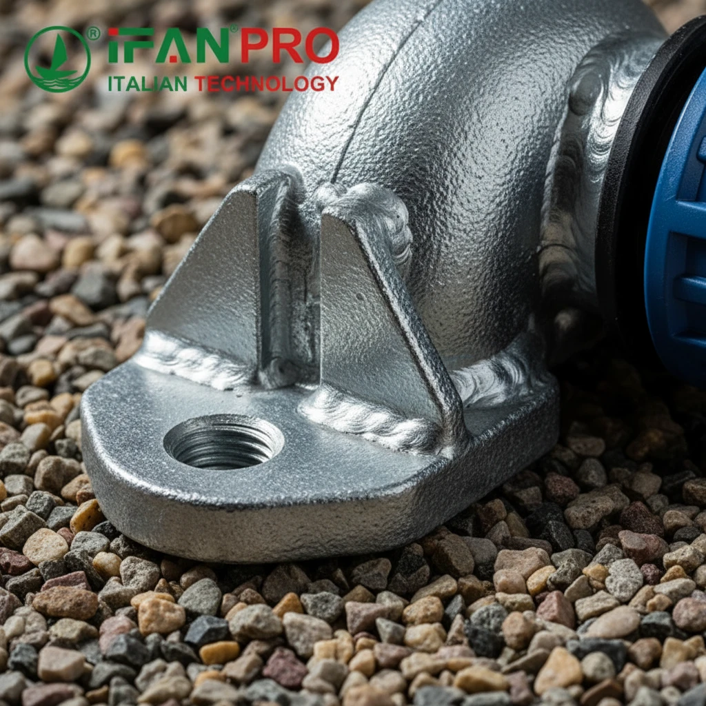
| Elbow slips out of the seat under pressure. | We design the seat with restraining lugs or a full 3/4 cradle geometry. We also specify the correct bolt torque if applicable. |
| Base plate bends or deforms. | We use thicker-grade steel (e.g., SS304, Q235B) and add reinforcing ribs (stiffeners) welded to the underside of the plate. |
Material and Finish Considerations
For direct burial, material choice is crucial because the seat is constantly in contact with soil and moisture. Therefore, we recommend hot-dip galvanized steel or stainless steel for excellent corrosion resistance. Moreover, the coating must be robust to withstand abrasion from rocks and gravel during backfilling.
How Can Anchor Bolt Holes or Lugs Be Integrated into the Custom Elbow Seat Design?
Anchor points transform a passive seat into an active restraint system. However, their integration must be both deliberate and strong.
Designers integrate anchor bolt holes or lugs by welding them to the sides or base of the main seat structure before galvanizing. They must design lugs with ample steel thickness and reinforce them with gussets. Additionally, bolt holes must be precisely sized and located to match standard anchor rod diameters and allow for minor field adjustment during installation.
The Role of Anchoring
While direct burial relies on soil friction and the seat’s geometry, mechanical anchoring provides a guaranteed, measurable level of restraint. This is critical in soft soils, high-pressure applications, or areas with seismic activity. Essentially, anchors physically tie the seat to a concrete foundation or a stable underground structure.
Design Integration Methods
There are two main ways to add anchoring: bolt holes and welded lugs.
Bolt Holes in the Base Plate: This is the cleanest method for concrete anchorage. Fabricators drill or punch large holes through the base plate itself. For this to work, the plate must be very thick to prevent tearing around the hole. We often add a welded steel washer or doubler plate around each hole on the underside for extra strength. Typically, the hole diameter is 1.5 times the bolt diameter to allow for placement tolerance.
Welded Attachment Lugs: These are more versatile. Lugs are steel plates or loops welded to the sides or top of the seat cradle. They provide a point to attach chains, cables, or bolts that can anchor to nearby structures or deadman anchors in the trench. The key to successful lug design is reinforcement.
Critical Reinforcement: Avoiding Failure Points
A lug welded onto a flat surface creates a weak point. Under constant tension, it can rip off. To prevent this, we use gussets or stiffener plates. These are triangular pieces of steel welded between the lug and the main body of the seat. They distribute the pulling force over a much larger area, making the connection extremely strong.
Design Specification Table
Here is a guide for integrating anchor points based on application:
| Application Scenario | Recommended Anchor Type | Key Design & Installation Advice |
|---|---|---|
| Buried in firm soil, moderate pressure | Optional lugs for safety. | Lugs provide a “belts and suspenders” backup to soil restraint. |
| Secured to a concrete thrust block | Bolt holes in base plate. | Use epoxy-set anchor bolts. Ensure the hole pattern is precise. |
| Soft, sandy, or unstable soil | Mandatory lugs or bolt holes. | Anchor to a separate, deeper concrete foundation or deadman. |
| High-pressure or surge-prone line | Mandatory heavy-duty lugs with gussets. | Use rated shackles and rods; specify a pull-out force requirement. |
Common Installation Error to Address
A major pain point is misalignment. If the anchor bolt holes in the seat don’t line up with the bolts cast in concrete, installers might force it, bending the seat. Our solution is to design slotted holes instead of round ones. This allows for several centimeters of adjustment in one direction, making field installation much faster and eliminating stress on the seat.
What Soil Condition Considerations Influence the Design of a Buried Elbow Seat?
Soil is not just dirt; it’s a living, changing material that directly challenges your design. Therefore, ignoring soil conditions guarantees future problems.
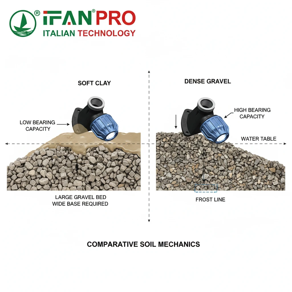
Soil conditions dramatically influence seat design because they determine the required size, anchoring need, and material protection. Key factors include soil type (clay, sand, rock), corrosiveness, moisture content, and frost line depth. For example, a seat for soft, wet clay needs a much larger footprint and stronger anchors than one for dense, dry gravel.
Why Soil Analysis is the First Step
You wouldn’t build a house without checking the ground. Similarly, you must analyze the soil before burying a critical pipeline component. The soil provides the support and the resistance against movement. Understanding its properties lets us design a seat that works with the ground, not against it until it fails.
Breaking Down Soil Factors
1. Soil Type and Bearing Capacity:
This is the most critical factor. The bearing capacity refers to how much weight a square unit of soil can hold without sinking.
- Soft Clay/Silt: Has low bearing capacity. It acts like wet plastic. Consequently, a seat here needs a very large base area to spread the load. It may also require deep pilings or a concrete slab underneath.
- Loose Sand: Can shift and settle. It has medium bearing capacity but poor cohesion. Therefore, a seat here needs good sidewall contact for friction and often mechanical anchors.
- Dense Sand/Gravel: Has high bearing capacity and good drainage. As a result, a standard, well-sized seat often works here.
- Rock: Has the highest capacity. In this case, the focus shifts from preventing sinking to providing a level surface and designing anchors that workers can drill into the rock.
2. Corrosiveness:
Some soils are chemically aggressive. For instance, acidic soils, soils with high salt content (near coasts), or soils with stray electrical currents accelerate corrosion.
- Design Impact: This factor dictates the material and coating. For highly corrosive soils, standard galvanization may not be enough. Therefore, we specify thicker coatings or upgrade to stainless steel (e.g., SS316) for the entire seat.
3. Moisture and Frost:
Water changes everything. Saturated soil becomes heavier (increasing load) and weaker (reducing bearing capacity). In freezing climates, frost heave presents a major threat.
- Frost Heave: When water in the soil freezes, it expands upward, lifting anything in it unevenly. This process can snap pipes.
- Design Impact: Installers must place the seat below the frost line. Furthermore, the design must ensure excellent drainage (weep holes, gravel bed) to keep water away from the base. In severe cases, engineers may need to anchor the seat to a foundation that extends below the frost line.
Soil-Specific Design Matrix
| Soil Condition | Primary Threat | Key Seat Design Adjustments |
|---|---|---|
| Soft, Cohesive Clay | Sinking (settlement), slow shifting. | Maximize base plate area. Use integrated skids or lower onto a gravel bed. Consider a concrete mat. |
| Loose, Granular Sand | Sudden shifting, washout from water flow. | Use a full cradle design for soil grip. Include mandatory mechanical anchors (lugs). Specify filter fabric and proper compaction. |
| Expansive Clay | Severe swelling when wet, shrinking when dry. | Design for extreme movement. Use a very deep, stable foundation isolated from the active soil layer. |
| High Water Table | Buoyancy (flotation), corrosion. | Increase seat weight/mass. Ensure large, clear weep holes. Upgrade to premium corrosion protection. |
| Frost-Susceptible Soil | Frost heave lifting the seat unevenly. | Bury seat below local frost depth. Perfect drainage is critical. Anchor to a deep foundation. |
Our Practical Advice
Always request a soil report for the project site. If one isn’t available, assume the worst common local conditions and design conservatively. Ultimately, it is cheaper to add more steel at the design stage than to excavate and repair a failed installation years later.
Are There Standard Guidelines for Anchoring HDPE Elbows in Trenchless Installations?
Trenchless installations like directional drilling present unique challenges. Fortunately, industry standards provide a clear roadmap for success.
Yes, key standards guide the anchoring of HDPE elbows in trenchless work. Specifically, ASTM F1962 covers directional drilling of PE pipe and emphasizes the need for restrained fittings. As a result, the design focus shifts to creating a solid, encapsulated “anchor block” around the elbow and seat. Contractors achieve this by using flowable fill or controlled low-strength material (CLSM) within the drilled cavity to transfer loads to the surrounding soil.
The Trenchless Challenge
In trenchless technology, you can’t simply dig a wide hole to pour a concrete thrust block. Instead, crews pull the elbow into a narrow, drilled hole. The surrounding soil is often disturbed, so creating stability becomes more complex. The goal is to build an anchor in-situ (in place) that is as effective as a traditional thrust block.
Following the Standards
The primary standard in North America is ASTM F1962 – Standard Practice for Directional Drilling of Polyethylene Pipe. This document is essential. It specifically states that all fittings, including elbows, in a directionally drilled PE pipeline must be restrained from pull-out and separation. However, it does not specify a single method, which places the emphasis on correct engineering design.
The Standard Method: Creating an Anchor Block
The industry-accepted solution is to construct an encapsulated anchor block. Here is how it works, step by step:
- Pull the Assembly: Crews pull the HDPE elbow, pre-welded to the pipes and securely mounted on its custom-designed seat (with lugs), into place at the desired bend location in the drilled path.
- Excavate an Anchor Chamber: At the elbow location, workers make a small, targeted excavation to create a cavity around the elbow that is larger than the drilled hole.
- Position and Anchor: They position the seat correctly. If designed with lugs, workers can temporarily brace or tie it to ensure it doesn’t move during the next step.
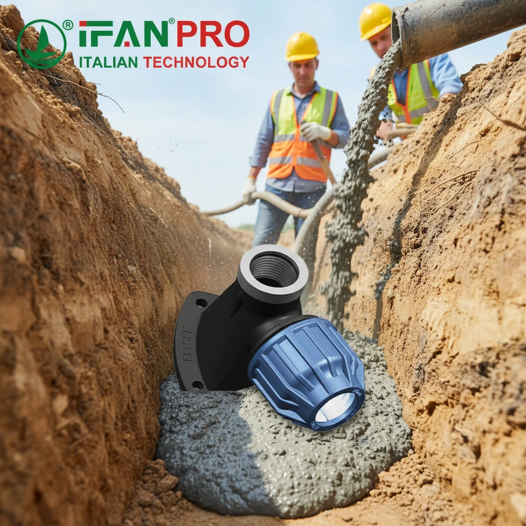
- Encapsulate with Flowable Fill: Crews completely fill the cavity with a flowable fill material, often called CLSM or “controlled density fill.” This material is like a soupy, strong concrete that flows into every space, fully encasing the elbow and its seat.
- Load Transfer: As the pipe tries to move from pressure, the force transfers from the elbow to the seat, from the seat to its lugs, and from the lugs into the massive, solid block of flowable fill. Subsequently, the fill block transfers these forces to the undisturbed soil walls of the cavity.
Key Design and Material Specifications
For this to work, the seat design and materials must align with the standard.
Seat Design for Trenchless: The seat must have heavy-duty lugs or loops. These are not optional; they are the critical interface that transfers force from the metal seat into the encapsulating fill. The fill bonds to and around these lugs, creating a monolithic lock.
Material Specifications: The flowable fill must meet certain standards for strength and flow. Common specifications include:
- Compressive Strength: Typically 50 to 100 psi (0.35 to 0.7 MPa) – it needs to be strong but not as hard as structural concrete.
- Flowability: It must be self-leveling and able to fill the cavity without vibration, leaving no air pockets.
Guideline Summary Table
| Standard / Guideline | Key Focus Area | Practical Implication for Seat Design |
|---|---|---|
| ASTM F1962 | Practice for directional drilling of PE pipe. | Mandates restraint for all fittings. Validates the encapsulated anchor block method. |
| Pipeline Industry Practice | Design of thrust restraint. | Specifies that engineers must calculate the anchor block size (volume) based on pipe diameter, pressure, and soil type. |
| Material Standards (CLSM) | Properties of flowable fill. | Seat lugs must be designed to be fully embedded and bonded within this material. |
| Corrosion Protection | Long-term integrity. | The seat must be hot-dip galvanized or stainless, as it will be permanently encased in a wet, cementitious environment. |
Our advice is to never use a standard, non-restrained elbow seat for a trenchless application. Instead, the design must be customized for encapsulation, and the installation procedure must be planned to ensure the anchor cavity is correctly sized and filled.
Conclusion
A successful buried or anchored elbow starts with a seat designed for its specific soil, pressure, and installation method. For a custom-engineered solution that addresses these exact challenges, contact IFAN to discuss your project’s requirements.


Commentaires récents