
I once inspected a heating system where one room was always cold. The problem wasn’t the boiler; it was an unbalanced flow from a poorly sized cross fitting.
A symmetrical cross fitting, by its basic design, aims to provide balanced flow distribution. In an ideal system with equal pressure at all inlets, flow will divide evenly. However, in real-world plumbing and HVAC systems, achieving perfect balance requires careful attention to internal geometry, system pressure, pipe sizing, and often the use of balancing valves on the cross ports.
The promise of balance is why we use crosses. But the reality is more complex. So, let’s dive into the details of how flow really behaves in a cross and how to control it.
How Does the Internal Geometry of a Cross Influence Flow to Each Branch?
You might think all four-way fittings are the same. I’ve seen two crosses from different factories cause completely different flow patterns due to subtle internal differences.
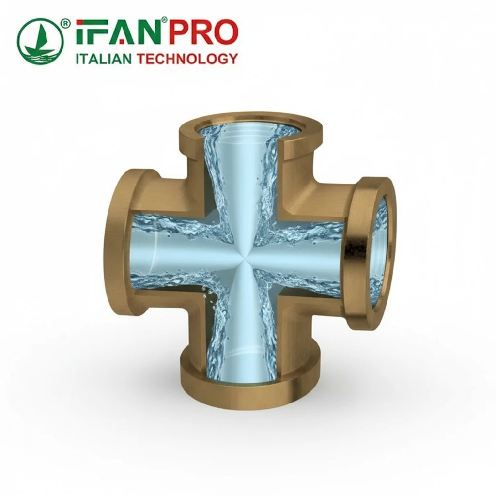
The internal geometry of a cross—specifically the smoothness of the bore, the sharpness of the intersecting corners, and the design of the flow path—directly influences turbulence and pressure drop. A well-made cross with a streamlined, rounded internal intersection creates less turbulence and a more predictable, balanced flow to each branch compared to a fitting with sharp, unfinished edges.
The Goal: Minimizing Turbulence
At the center of a cross, water or another fluid arrives and must make a decision: go straight, turn left, or turn right. How the fitting guides this decision is crucial. The primary goal of good internal geometry is to minimize turbulent flow. Turbulence creates energy loss in the form of pressure drop, which can be uneven and lead to unbalanced flow.
Think of it like a busy intersection. A well-designed, rounded intersection allows cars to flow smoothly in all directions. However, a jagged, poorly designed intersection causes crashes and traffic jams. This results in an uneven flow of cars down each road. It’s the same for fluid in a pipe cross.
Key Geometric Features
Here are the specific internal features that matter:
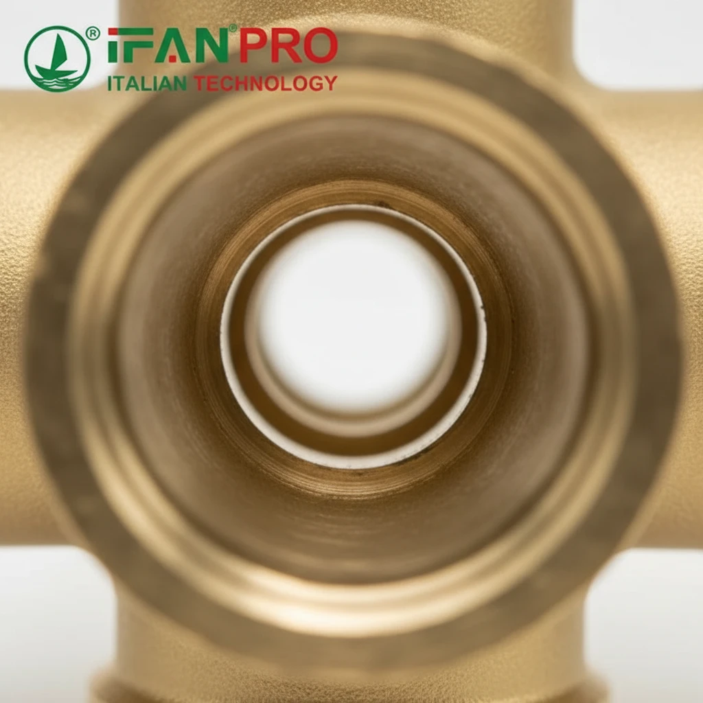
- Bore Smoothness: The inner wall of the fitting should be as smooth as the pipe itself. Rough surfaces create friction, slowing down the fluid. Consequently, this contributes to uneven pressure loss.
- Corner Radius: This is the most critical factor. A cross with a large, rounded internal corner at the intersections helps guide the fluid smoothly around the turn. In contrast, a sharp, 90-degree corner forces the fluid to make an abrupt change. This causes severe turbulence, eddies, and a significant localized pressure drop. As a result, the branch opposite the inlet might get less flow.
- Consistent Diameter: The internal diameter should match the nominal pipe size consistently. Any sudden narrowing (restriction) or widening will change fluid velocity and pressure unpredictably.
How Geometry Affects Balance
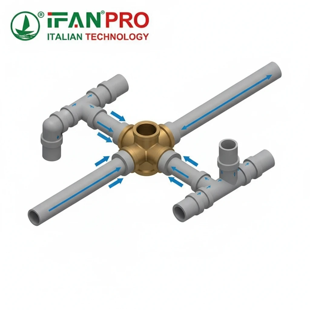
When flow enters one leg of the cross, the path of least resistance is usually straight through to the opposite port. For flow to divert equally into the two side branches, the internal design must offer very similar resistance to those turns. A symmetrical, well-radiused cross does this best. Conversely, a poorly molded cross with one side having a slightly sharper corner will send more flow to the branch with the smoother turn.
| Internal Geometry Feature | Effect on Flow | Result for Balance |
|---|---|---|
| Smooth, polished bore | Low friction, minimal pressure loss. | Promotes predictable, balanced flow. |
| Large, rounded corners | Smooth flow diversion, low turbulence. | Encourages equal flow to side branches. |
| Sharp, 90-degree corners | High turbulence, vortices, high pressure drop. | Causes uneven flow, starves opposite/side branches. |
| Inconsistent diameter | Changes in velocity and pressure. | Creates unpredictable, unbalanced distribution. |
Therefore, the cross’s internal geometry sets the baseline for its balancing potential. So, a high-quality fitting from a manufacturer like IFAN, which controls these molding details, is the essential starting point for any system where balance is important.
What Factors Can Cause Unbalanced Flow Even with a Symmetrical Cross?
Installing a perfect cross doesn’t guarantee perfect balance. I’ve traced countless imbalance issues back to factors outside the fitting itself.
Even with a perfectly symmetrical cross, unbalanced flow is commonly caused by factors external to the fitting: unequal pressure in the supply lines, different lengths or diameters of piping connected to each branch, and varying demand downstream. These factors change the system’s resistance, guiding flow toward the path of least resistance.
The System Resistance Network
A cross fitting is just one component in a larger system. Fluid flow follows the path of least resistance. Think of resistance like traffic congestion. Even if an intersection is perfect, the road leading north might be clear, while the road leading east is packed. Naturally, cars will choose the clear road.
In a piping system, “resistance” is created by:
- Pipe Length: Longer pipes have more friction.
- Pipe Diameter: Smaller pipes have much higher friction.
- Fittings: Elbows, tees, and valves add resistance.
- End-Use Devices: A heat exchanger or a closed valve represents a final point of resistance.
Common Culprits of Imbalance
Let’s break down the most frequent external causes:
1. Unequal Pipe Run Lengths:
This is the most common issue. If the pipe running from the cross to Radiator A is 10 feet long, but the pipe to Radiator B is 30 feet long, the path to B has more frictional resistance. Therefore, even with an identical radiator, more flow will go to A because it’s easier. The cross is just a point of division; it doesn’t correct for this.
2. Different Terminal Unit Types:
Not all branches serve the same device. One branch might feed a high-resistance fan coil unit, while another feeds a low-resistance radiator. Their inherent resistance to flow is different, so flow will not be 50/50.
3. Improper Pipe Sizing:
If one branch is piped with 3/4″ pipe and another with 1/2″ pipe, the smaller pipe creates much higher resistance. As a result, flow will favor the 3/4″ branch. Generally, all branches connected to a common cross should start with the same diameter.
4. Variable Downstream Demand:
This is a dynamic cause. Imagine a cross supplying four shower heads. If three showers are off, almost all the flow will rush to the one open shower. The cross is symmetrical, but the demand is not.
The System Dictates the Flow
The table below summarizes how external factors override the cross’s symmetry:
| External Factor | How It Creates Imbalance | Real-World Example |
|---|---|---|
| Different Pipe Lengths | Longer pipe = higher frictional resistance. | A bathroom farther from the water heater gets less hot water. |
| Different Pipe Sizes | Smaller pipe diameter = much higher resistance. | A branch reduced in size for convenience chokes flow. |
| Different End Devices | Devices have different pressure drop ratings. | A fancy showerhead vs. a simple tub spout on the same cross. |
| Varied Downstream Valves | Valves change the system’s resistance map. | Manually adjusting one radiator valve unbalances the whole loop. |
The takeaway is crucial: you cannot buy balance off the shelf in a fitting. In other words, balance is a system characteristic. The cross allows for distribution, but the rest of the system determines if that distribution is fair.
Can Flow Be Actively Balanced Using Valves on the Cross Ports?
Yes, absolutely. This is where theory meets practical engineering. Valves turn a passive cross into an active balancing component.
Flow can and should be actively balanced using valves on the cross ports. Installing manual balancing valves or automatic flow limiters on the outlet branches allows you to adjust the resistance of each path. By increasing resistance on high-flow branches, you can restrict their flow and force more fluid to the lower-flow branches, achieving a designed balance.

Why Valves Are the Solution
Remember, flow goes where resistance is lowest. If one branch has naturally low resistance, it will steal flow. Therefore, the solution is to artificially add resistance to that greedy branch until all paths have equal total resistance. Valves are perfect, adjustable resistors.
Types of Balancing Valves
There are two main approaches:
1. Manual Balancing Valves:
These are specialized valves, often with pressure tap ports and a calibrated handwheel. A technician measures the flow rate and adjusts the handwheel to set the flow to a pre-calculated design rate.
- How it works: The valve restricts the flow passage. Turning it clockwise increases resistance, reducing flow. Then, the technician adjusts each branch valve in sequence until all flows match the system design.
- Best for: Static systems where flow demands don’t change often, like baseboard heating.
2. Automatic Flow Limiting Valves:
These valves are “set-and-forget.” You pre-set them to a maximum flow rate. They automatically adjust their internal mechanism to maintain that flow rate.
- How it works: If pressure increases, the valve diaphragm constricts to prevent extra flow. Conversely, if pressure drops, it opens slightly to maintain the set flow.
- Best for: Systems with variable demands, like multi-zone domestic hot water recirculation.
The Balancing Process in Practice
Here is a simple step-by-step process for manual balancing:
- Design: An engineer calculates the required flow for each branch to meet its load.
- Install: Install a balancing valve on the outlet of every branch of the cross.
- Measure: Use a flow meter to measure the initial, “unbalanced” flow in each branch.
- Adjust: Start with the branch with the highest flow. Gently close its valve to increase resistance until its flow matches the design number.
- Repeat: Move to the next branch. As you restrict the high-flow branches, you will naturally see flow increase in the previously low-flow branches. Finally, adjust them to their design flow.
| Balancing Method | How It Works | Pro | Con |
|---|---|---|---|
| Manual Valve | Technician adjusts valve to a set position to create fixed resistance. | Lower cost, simple hardware. | Requires skilled labor; balance is lost if system changes. |
| Auto Flow Limiter | Valve self-adjusts to maintain a pre-set maximum flow rate. | Maintains balance dynamically; less commissioning time. | Higher initial cost per valve. |
| No Valves | Relies on perfect system symmetry. | Lowest cost. | Almost never works in real installations. |
Therefore, while the cross is the distribution point, the valves are the control panel. For this reason, specifying a cross with integral valve ports or planning for valve installation downstream is critical for any serious system design.
How Important Is Pipe Sizing and Layout for Achieving Balanced Distribution?
It is fundamentally important. Proper pipe sizing and layout are the foundation upon which balancing is built. In fact, trying to balance a poorly sized system is like trying to tune a piano with broken strings.
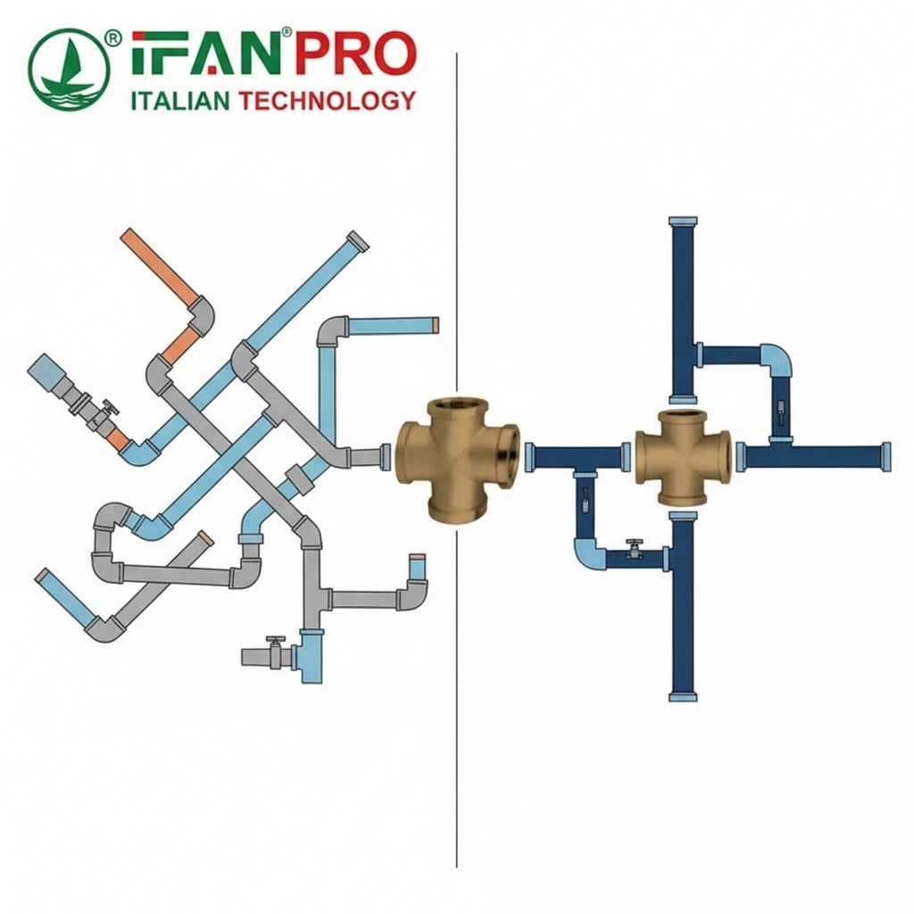
Pipe sizing and layout are critically important because they establish the baseline resistance of each flow path. Correct, consistent sizing ensures that no branch is inherently disadvantaged by excessive friction. Furthermore, a well-planned, symmetrical layout minimizes the need for extreme valve adjustments and makes the entire system more efficient and easier to balance.
Sizing: The First Rule of Hydronics
Pipe diameter has a massive, non-linear effect on flow resistance. For example, going from a 1/2″ pipe to a 3/4″ pipe for the same flow can reduce friction by over 80%. If branches off a cross are sized differently, you create a massive, built-in imbalance before any water even flows.
The Golden Rule: All branches serving similar loads and lengths should start with the same pipe size from the cross. This is not just a suggestion; it’s Hydronics 101. Additionally, the main supply trunk to the cross must also be sized to deliver enough flow and pressure to feed all branches simultaneously.
Layout: Striving for Symmetry
While perfect symmetry is rare in buildings, the goal is to get as close as possible. A good layout reduces the “balancing burden” placed on the valves.
Principles of a Balanced Layout:
- Home Runs: Where possible, run similarly sized pipes from the cross to each end device in a “home run” pattern. Avoid daisy-chaining devices on one branch if others have direct runs.
- Loop Systems: In heating systems, arrange the cross as part of a “reverse return” loop. This clever layout ensures that the total pipe length from the pump out and back is nearly identical for every branch, naturally promoting balance.
- Manifold Approach: In complex systems, use a cross as part of a central manifold with equal-length home runs to each zone. This is the most reliable way to achieve base balance.
The Cost of Getting It Wrong
Ignoring sizing and layout leads to chronic problems:
- Excessive Pumping Energy: The pump must work much harder to push water through undersized, high-resistance pipes.
- Unbalanceable Systems: You may fully close a balancing valve on a “greedy” branch and still not achieve enough flow to the “starved” branch. In other words, the system is fundamentally flawed.
- Noise and Wear: High water velocity in small pipes creates noise and accelerates erosion.
Foundation Before Fine-Tuning
To summarize, think of the system as a chain: Pump -> Piping Layout -> Cross -> Balancing Valves -> Devices. The cross is a critical link, but it cannot compensate for a weak link upstream or downstream. First, good sizing and layout create a fair starting point. Then, balancing valves make the final fine adjustments. Ultimately, this two-step process ensures reliable performance.
Conclusion
A cross fitting enables distribution, but true balance requires a holistic system design with proper sizing, layout, and the mandatory use of balancing valves. For reliable flow control, specify high-quality crosses and valves from IFAN.


Commentaires récents