
PEX pipe fittings sizes look like the simplest spec in a plumbing catalogue. A 1/2-inch fitting goes on 1/2-inch tube, a 3/4-inch fitting goes on 3/4-inch tube, and the purchase order writes itself. That works right up until a container of technically-correct fittings lands somewhere the threads do not match the local pipework, or a finished riser fails its flow test with every joint installed exactly as specified.
The reason is that a PEX fitting size is a name, not a dimension. It tells you which tube the fitting grips. It says nothing about the hole water actually travels through. Take one grounded example: ASTM F1807, the metal insert crimp standard, sets a minimum inside diameter of 0.350 in for a 1/2-inch fitting. The inside diameter of 3/8-inch PEX tube is also 0.350 in. So a correctly-made, code-listed 1/2-inch crimp fitting necks your line down to exactly a 3/8-inch bore for the length of the joint. That number is in the standard, not in the catalogue, and it is the number this chart is built around.

Key Takeaways
- A fitting’s size names the tube it grips, not its bore. ASTM F1807 minimum inside diameters are 0.350 in at 1/2 in, 0.530 in at 3/4 in and 0.710 in at 1 in.
- A brass F1807 insert fitting costs you 45.7% of the flow area at 1/2 in, 38.7% at 3/4 in and 32.3% at 1 in, calculated against real tube bores.
- Poly-alloy F2159 fittings are tighter again because the standard demands a thicker wall — 0.056 in against 0.028 in at 1/2 in — giving 19.0% to 26.2% less flow area than brass in the same nominal size.
- 1-1/4 in exists in F1807, F1960, F2080 and F2434, but not in F2159 — the plastic insert standard stops at 1 in, so a 1-1/4 in poly-alloy crimp fitting is not a real part.
- NPT is 60° and BSP is 55°. At 1 in nominal they are 11.5 and 11 threads per inch: close enough to start by hand, never close enough to seal.
- Tapered threads (NPT, BSPT/R) seal on the flanks with sealant; parallel threads (BSPP/G, Eurocone G3/4) seal on a washer or O-ring at the face. Buying the wrong family buys a leak.
- A UK 15 mm PEX system and a US 1/2 in CTS system are different pipes. 15 mm tube is not 0.625 in tube, and their fittings do not cross over.
How PEX Fitting Sizes Are Actually Named
PEX tube is outside-diameter controlled. ASTM F876 builds it to a nominal SDR9 — standard dimension ratio 9, meaning the wall is a ninth of the average outside diameter — and pins the dimensions to copper tube size (CTS) up to 1-1/4 in, switching to iron pipe size (IPS) at 1-1/2 in and above. The practical consequence is the one that catches people out: a “1/2-inch” PEX tube measures 0.625 in across the outside. Nothing about it is half an inch. The nominal figure is a naming convention inherited from copper, and every fitting sold against it inherits the same convention.
Because the tube is OD-controlled, an insert fitting has to be built to the inside of that tube. Its barb is sized to the tube bore, its own wall thickness sits inside the barb, and whatever is left in the middle is the water path. That ordering is why the bore is always the smallest number in the assembly, and why it never appears in the size name. Wall thickness tolerance on the tube is ±12% of nominal, so the bore you actually get has a spread even before the fitting goes in.
Here is a discrepancy worth knowing about before you compare charts. Most published PEX size tables derive the inside diameter from SDR9 arithmetic: 0.625 OD minus twice a 0.070 nominal wall gives 0.485 in for 1/2-inch. Real production tubing is walled thicker than the nominal minimum, because a manufacturer building to the minimum has no tolerance left. One lead-free non-barrier PEX data sheet lists a 1/2-inch wall of 0.070 in ±0.01 and states the resulting bore as 0.475 in, not 0.485 in. At 3/4 in the gap is wider: 0.677 in against the 0.709 in the nominal maths predicts. Neither figure is wrong, but they answer different questions, and only the data-sheet figure describes the pipe on the pallet. Every calculation in this guide uses the data-sheet numbers.
The four dimensions a fitting spec should give you
A submittal sheet worth trusting states four things per size, and a catalogue page that gives you only the first is not a spec. The dimensional requirements quoted below sit in ASTM F1807-26, the current edition of the metal-insert standard. The PEX fitting connection types comparison covers how each joining method behaves in the field; what follows is the dimensional layer underneath it.
- Fitting inside diameter (the bore): the actual water path. F1807 sets minima of 0.230 in at 3/8 in, 0.350 in at 1/2 in, 0.530 in at 3/4 in and 0.710 in at 1 in.
- Barb diameter: what grips the tube. F1807 gives 0.345 in, 0.471 in, 0.667 in and 0.856 in for those same sizes, each held to ±0.004 in. That tolerance is tight for a reason — it is the seal.
- Fitting wall thickness: the difference between barb and bore. Brass F1807 minima run 0.025 in, 0.028 in, 0.037 in and 0.041 in.
- Fitting end length: how much barb enters the tube. F1807 requires at least 0.625 in on every size from 3/8 in to 1 in, which is what a crimp ring has to sit over.
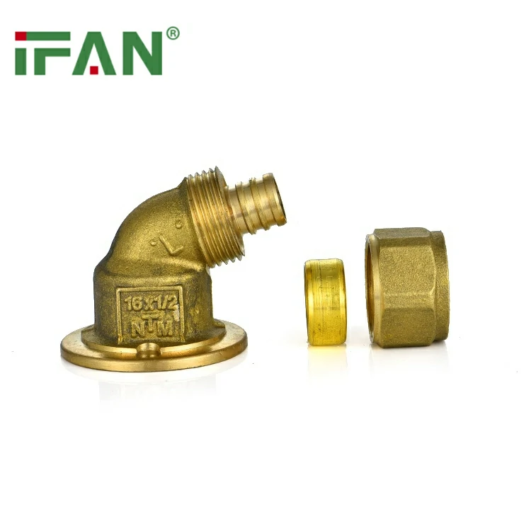
The Full PEX Fitting Size and Bore Chart
Two tables do the work. The first is the dimensional chart across the sizes that exist in both the metal-insert and plastic-insert standards, with the tube bore alongside so the loss at each joint is visible rather than implied. The second maps which standard covers which size, because that is what determines whether a part you want to order is manufacturable at all.
| Nominal size | Tube OD / bore (in) | F1807 brass bore (in, min) | F2159 poly bore (in, min) | Barb dia (in) |
|---|---|---|---|---|
| 3/8 in | 0.500 / 0.350 | 0.230 | in scope, not published | 0.345 ±0.004 |
| 1/2 in | 0.625 / 0.475 | 0.350 | 0.315 | 0.471 ±0.004 |
| 3/4 in | 0.875 / 0.677 | 0.530 | 0.460 | 0.667 ±0.004 |
| 1 in | 1.125 / 0.863 | 0.710 | 0.610 | 0.856 ±0.004 |
| 1-1/4 in | 1.375 / see note | in scope, not published | not in scope | in scope, not published |
Where the table says “in scope, not published,” the size is genuinely covered by the standard but the submittal sheets used here run only to 1 in, so no bore figure is quoted rather than an invented one. Ask any supplier for their own dimensional sheet at 1-1/4 in and above. One deliberate omission is worth naming, because a radiant specifier will spot it: F1807 covers eight nominal sizes — 3/8, 1/2, 5/8, 3/4, 1, 1-1/4, 1-1/2 and 2 in — and 5/8 in is missing from the rows above. It is in the standard’s scope, but none of the submittal sheets used for this chart publishes a bore, barb or wall figure at 5/8 in, so it is omitted rather than interpolated. Do not estimate it from the 1/2 in and 3/4 in rows: bore is set by wall thickness, wall thickness does not scale linearly across sizes, and the F1807 minima above prove it (0.028 in at 1/2 in, 0.037 in at 3/4 in). If your loop schedule calls for 5/8 in, ask for the maker’s dimensional sheet at that size specifically and treat quoted availability as unconfirmed until you have it. The F1807 and F2159 bores, barbs and wall thicknesses come from manufacturer submittal sheets whose tables are headed “DIMENSIONS per ASTM F1807” and “DIMENSIONS per ASTM F2159” — they are the standards’ minima, not one brand’s design preference, which is why they are usable as a buying baseline.
| Standard | What it covers | Size range | Rating |
|---|---|---|---|
| ASTM F1807 | Metal insert + copper crimp ring or SS clamp | 3/8 to 2 in (8 sizes) | 100 psi at 180°F |
| ASTM F2159 | Sulfone plastic insert + copper crimp ring | 3/8 to 1 in only | 100 psi at 180°F |
| ASTM F1960 | Cold expansion + PEX reinforcing ring | 3/8 to 2 in | 100 psi at 180°F |
| ASTM F2080 | Cold expansion + metal compression sleeve | 3/8 to 2 in | 100 psi at 180°F |
| ASTM F2434 | Metal insert with O-rings, PEX and PEX-AL-PEX | 1/2 to 1-1/4 in | 100 psi at 180°F |
| ASSE 1061 | Push-fit fitting performance | up to 2 in | per standard |
Every one of these systems is rated 100 psi at 180°F, which is a useful thing to notice: the joining method is not a pressure-class decision. They differ on size availability, on bore, on tooling and on which PEX type they suit — never on the headline rating. Scope figures here come from the Plastics Pipe Institute’s residential PEX design guide, which reproduces the ASTM scopes with permission.
The Number That Decides Flow: Fitting Bore, Not Fitting Size
Flow follows area, and area follows the square of the diameter. That is why a bore reduction that sounds mild in inches is severe in flow terms. Run the areas on the grounded diameters and the 1/2-inch case comes out at 0.1772 in² for the tube bore against 0.0962 in² through a brass F1807 fitting — a 45.7% loss of cross-section. At 3/4 in the loss is 38.7%, at 1 in it is 32.3%. The penalty shrinks as the pipe grows, because fitting walls do not scale as fast as bores do, but it never disappears.
Poly-alloy insert fittings to F2159 are tighter again, and the standard itself explains why. F2159 requires a far thicker fitting wall than F1807 in the same nominal size: 0.056 in against 0.028 in at 1/2 in, 0.082 in against 0.037 in at 3/4 in, 0.100 in against 0.041 in at 1 in. Sulfone plastic is not brass, so it needs the section to hold pressure. The barb outside diameter is fixed by the tube, the wall grows inward, and the bore is what pays. Net effect, same maker and same nominal size: poly-alloy gives 19.0% less flow area than brass at 1/2 in, 24.7% less at 3/4 in and 26.2% less at 1 in.
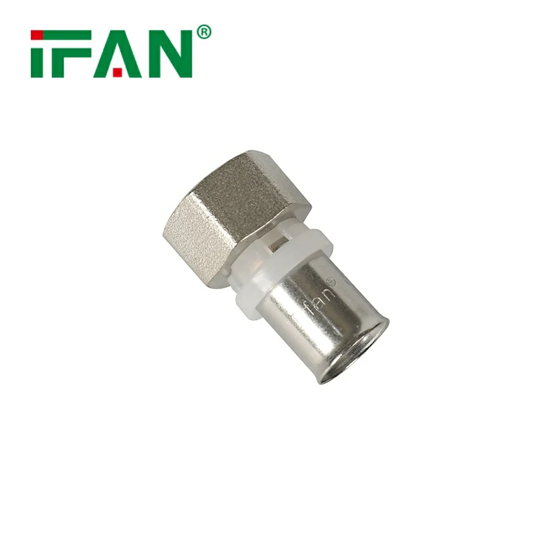
This is where the 1/2-inch coincidence earns its place in a buying decision. The F1807 minimum bore at 1/2 in is 0.350 in. The measured tube bore at 3/8 in is 0.350 in. Two independent sources, the same figure — so at every 1/2-inch insert joint, the line is briefly a 3/8-inch line. For scale, the same tubing data sheet puts pressure loss at 2.0 GPM at 26.1 psi per 100 ft for 3/8-inch and 5.30 psi per 100 ft for 1/2-inch: 4.92 times the loss. A joint is not 100 ft long, so no single fitting does that damage. Twenty of them on a long branch, though, is a real number, and it is the number that never gets modelled because the fitting schedule and the pipe schedule are usually costed by different people.
Where cold expansion changes the arithmetic
Insert fittings go inside the tube, so they must be smaller than it. Cold expansion inverts the geometry: the tube is expanded and pulled over the fitting, with the reinforcing ring outside that, so the fitting body is not competing with the tube for the same space. F1960 assemblies run noticeably closer to full bore than any insert system. That is a structural consequence of the joint, not a marketing claim — but the honest position is that the size of the advantage varies by manufacturer and no F1960 bore table is quoted here because none was available at a standard-level source. If flow margin is the deciding factor on a project, make the supplier put their own bore figures in writing and compare those, not the connection type in the abstract.
The same caution applies to per-fitting equivalent lengths. Elbows and tees add more loss than a straight coupling of the same bore, and design guides handle this with equivalent-length or K-factor tables. No such table for PEX insert fittings could be verified at a standards-body or manufacturer source for this guide, so none is reproduced. Treat the bore reduction above as the part you can calculate, and get equivalent lengths from the maker’s own engineering data before committing a long-run design.
Size by Size: 1/2, 3/4, 1-inch and 1-1/4
Four sizes carry almost all the volume in a PEX fitting order, and each has a distinct failure mode. Worth reading against the PEX pipe sizing chart, which handles the tube side of the same decision in detail — flow rates, pressure by temperature and fixture sizing.
1/2 inch — the volume line, and the tightest bore
This is the fixture-drop size and usually the largest line item on the order. It is also where the bore penalty bites hardest, at 45.7% in brass and 56.0% in poly-alloy. The buying implication is specific: 1/2 in is the size where the brass-versus-poly decision is worth paying for, because it is the size where the difference between 0.350 in and 0.315 in is a fifth of the flow area. On a short drop to a basin, nobody will notice. On a long branch feeding a shower at the end of a run, the same fitting choice is the difference between a compliant flow test and a callback.
3/4 inch — where the wall-thickness jump lands
Trunk and manifold-feed size. Two things change here. Brass fitting wall minimum steps from 0.028 in to 0.037 in, and tube wall steps from 0.070 in to 0.097 in, so both sides of the joint get heavier. And the poly-alloy penalty widens rather than narrows: 24.7% less flow area than brass, against 19.0% at 1/2 in. If a supplier offers a mixed order that quietly substitutes poly-alloy at 3/4 in to hold a price, that substitution costs more flow than the same swap at 1/2 in — the opposite of what most buyers assume.
1 inch — the last size both insert standards reach
Main service and large distribution loops. The bore penalty is at its mildest here, 32.3% in brass, and 1 in is the ceiling of the F2159 plastic insert standard. Above this size, poly-alloy insert fittings stop existing, so the material choice makes itself. It is also the size where barb diameters converge: F1807 and F2159 both specify 0.856 in at 1 in, differing only in tolerance (±0.004 in against ±0.003 in). The barbs are interchangeable in the tube; the bores are not.
1-1/4 inch — the size that exposes a catalogue error
1-1/4 in is real in F1807, F1960 and F2080, all of which run to 2 in, and it is the top of F2434’s 1/2-to-1-1/4-in range for PEX-AL-PEX. It does not exist in F2159, whose scope stops at 1 in. So a quotation offering 1-1/4 in poly-alloy crimp fittings is describing a part that no standard covers — either it is mislabelled, or it is being made outside the specification it claims. That single check has saved buyers a container. This is also the size where CTS naming ends: at 1-1/2 in and above, F876 switches to iron pipe size, so fitting dimensions stop tracking the copper convention entirely.
NPT, BSP and Metric: Reading the Thread Half of the Spec
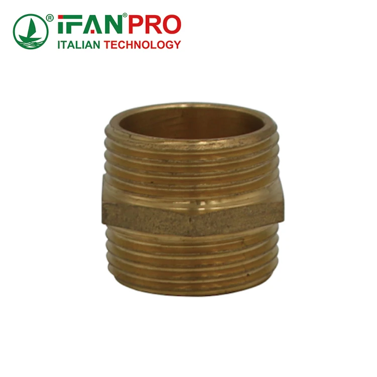
Half of a PEX fitting order is not PEX at all. Every transition to a valve, a manifold, a water heater or existing pipework happens on a thread, and threads are where a technically-correct order goes wrong across borders. Two families dominate. NPT, to ASME B1.20.1, is North American: 60° flank angle, flat crests and roots, tapered 1:16. BSP is the standard almost everywhere else, using the Whitworth form at 55° with rounded crests and roots, and splitting into two sub-families — ISO 228-1 parallel threads (designated G) and ISO 7-1 tapered threads (R, Rc, Rp).
| Size | NPT TPI | BSP TPI | NPT major dia (in) | BSP major dia (mm) |
|---|---|---|---|---|
| 3/8 in | 18 | 19 | 0.6750 | 16.662 |
| 1/2 in | 14 | 14 | 0.8400 | 20.955 |
| 3/4 in | 14 | 14 | 1.0500 | 26.441 |
| 1 in | 11.5 | 11 | 1.3150 | 33.249 |
| 1-1/4 in | 11.5 | 11 | 1.6600 | 41.910 |
Read the 1/2 in and 3/4 in rows and you can see the trap. Both are 14 threads per inch in both systems. The pitches match exactly, so an NPT male will thread into a BSP female and feel entirely normal going in — while the 60° flank sits against a 55° flank on a rounded root, contacting on a fraction of the intended area. It tightens, it holds a pressure test sometimes, and it weeps weeks later under thermal cycling. At 1 in and 1-1/4 in the mismatch is coarser, 11.5 against 11, so the joint binds partway and at least announces itself. The dangerous sizes are the ones that fit.
Tapered or parallel decides where the seal lives
This distinction matters more than the flank angle in practice. Tapered threads — NPT, BSPT/R — wedge as they tighten and seal on the thread flanks themselves, which is why they need PTFE tape or a pipe sealant to fill the helical path. Parallel threads — BSPP/G, and metric — do not wedge at all; they seal on a flat face against a washer or an O-ring, and the thread only supplies clamping force. Put sealant on a parallel thread and it does nothing useful. Omit the washer and no amount of torque will stop the leak. A crate of parallel-thread fittings delivered to a site expecting tapered ones cannot be rescued with tape.
Metric systems and the Eurocone
Continental European PEX runs on metric outside diameters — 16, 20, 25 and 32 mm — and lands on manifolds through a Eurocone connection: a G3/4 in parallel BSP thread with a conical seat, typically rated 10 bar and 95°C, with the pipe held by a compression olive and the seal made on the cone. UK and Irish systems add a further wrinkle. British metric PEX uses copper-equivalent sizes of 10, 12, 15, 22 and 28 mm, and one manufacturer’s data sheet gives 15 mm tube a 1.5–1.8 mm wall while its separate Irish 1/2 in size measures 14.63–14.74 mm outside diameter with a 1.6–1.8 mm wall. Those are two different pipes with two different fitting sets, sold into markets a ferry apart.
So “1/2 inch PEX fittings” resolves to at least three incompatible things depending on where the container is going: 0.625 in CTS in North America, roughly 14.7 mm in Ireland, and 15 mm nominal in Britain. None of them accepts the others’ fittings. Confirm the destination market’s dimensional standard — ASTM F876 and F877, EN ISO 15875, DIN 16892, BS 7291 or GB/T 18992 — in the order itself, because the nominal size on a purchase order does not carry that information and requirements vary by market and by the role you hold in the supply chain.
European pipe standards also rate differently from the ASTM 100 psi at 180°F convention. BS 7291 Class S, for instance, is specified at 12 bar at 20°C, 4 bar at 82°C and 3 bar at 92°C, with short-term overload tolerance to 114°C. A fitting matched to the pipe standard rather than to a habit is the only way that stays consistent.
Which PEX Fitting System Fits Your Market
Fitting systems are not better or worse in general; they are matched or mismatched to a market’s tooling, code and pipe standard. The blunt position: if you are stocking for North American plumbers, brass F1807 is the default and everything else is a line extension, because crimp tooling is already in every van and F1807 works with all PEX types. If you are stocking for continental Europe or the Middle East, compression and press systems on metric pipe are the default and F1807 is close to irrelevant.
| System | Best for | Not ideal for |
|---|---|---|
| Brass insert, F1807 | North American stock, all PEX types, 3/8–2 in breadth | Aggressive or low-pH water where dezincification is a risk |
| Poly-alloy insert, F2159 | Price-led lines, poor water quality, short drops | Long branches, sizes above 1 in, flow-critical risers |
| Cold expansion, F1960 | PEX-a systems, flow-critical work, larger sizes | Mixed-brand PEX-b stock, crews without expansion tools |
| Compression / Eurocone | EU, UK and Middle East metric pipe, manifold work | CTS-sized North American tube, buried joints |
| Push-fit, ASSE 1061 | Repairs, retail channel, tool-free installs | High-volume new build on unit cost |
| Insert with O-rings, F2434 | PEX-AL-PEX systems, 1/2–1-1/4 in | Plain PEX-only ranges, sizes above 1-1/4 in |
The one genuine trade-off in that table is poly-alloy. It gives up a quarter of the flow area at 3/4 in — 24.7% against brass, on the grounded bores above — and it is the right choice anyway where water chemistry attacks brass, because plastic does not dezincify. That is a real engineering reason to accept a bore penalty, and it is different from accepting the same penalty because a quotation came in cheaper. Know which of the two you are doing.
One warning about switching systems to chase a bore. Every insert system needs its own calibrated tool, and F1960 needs an expansion head per size; F2098 clamps cover only four sizes, so a crew standardised on clamps cannot simply follow you up the size range. A buyer who moves a stocked line from crimp to expansion to gain flow area has also just obsoleted the tooling in their customers’ vans, and that objection surfaces after the first container, not during the quotation. Change the system when the pipe standard or the water chemistry demands it — not to win a flow argument on paper.
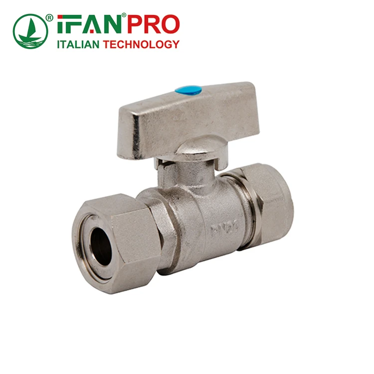
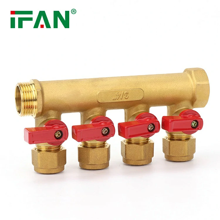
IFANPRO builds PEX compression fittings against BS 7291, DIN 16892 and GB/T 18992, alongside PEX press fittings, brass PEX union and valve bodies, and the 121UC union for PEX-AL-PEX — which is the practical answer to why a single supplier can serve both a UK merchant and a Gulf contractor from one factory. The PEX pipe and fittings range is organised by system rather than by size for exactly this reason: the system decision comes first, and the size chart applies inside it.
A Worked Example: Sizing a 3/4-inch Trunk Through Its Fittings
Take a 3/4-inch PEX trunk carrying 6 GPM — a realistic figure for a branch serving several fixtures at once. The relevant design ceiling is velocity: adopted plumbing code text limits water supply piping to 8 fps at maximum probable demand, to control noise and cavitation, dropping to 4 fps where a branch feeds a quick-closing device and 2 fps in continuous hot-water circulation. PEX manufacturers use the same 8 ft/s figure as a maximum recommended flow velocity.
Run the velocity three times, once for each bore the water meets. Through the tube itself, 0.677 in, the water moves at 5.35 ft/s — comfortable, well inside the limit, and this is the only number a tube-only calculation ever produces. Through a brass F1807 fitting at 0.530 in, it accelerates to 8.73 ft/s. Through a poly-alloy F2159 fitting at 0.460 in, it hits 11.58 ft/s.
The pipe passes at 5.35 ft/s. The brass fitting is already over the 8 fps limit at 8.73 ft/s. The poly-alloy fitting reaches 11.58 ft/s — a velocity plastics survive mechanically but announce audibly.
Two conclusions come out of that, and both are actionable. First, the noise complaint that arrives after handover is often not a pipe-sizing error at all — the pipe was sized correctly and the fittings were never in the calculation. Second, the fix is rarely to upsize the whole trunk. Changing the fitting system on the flow-critical section, or stepping the trunk up one size only where fitting density is highest, addresses the actual restriction at a fraction of the material cost. A buyer who can explain this to a specifier is selling a solution rather than a discount, and it is worth reading alongside how fitting stress affects PEX service life, since sustained high velocity at a joint is one of the conditions that shortens it.
One caveat, stated plainly: these are steady-state velocities through each bore, not a full pressure-loss model. A complete calculation would add per-fitting equivalent lengths, and those numbers have to come from the manufacturer’s engineering data rather than from a general chart. The velocity comparison is enough to show which component governs, which is the decision this example exists to inform.
What to Check Before You Approve a PEX Fitting Order
This is the documented sequence for checking a PEX fitting specification before a container is cut, ordered so that the cheapest checks catch the most expensive errors first. Every step is a document review or a measurement, not a judgement call.
- Match the fitting standard to the pipe standard, not to the size: F1807, F2159, F1960, F2080 or F2434 for ASTM systems; EN ISO 15875, DIN 16892, BS 7291 or GB/T 18992 for metric. A fitting standard that does not name your pipe standard is the wrong fitting.
- Check the size exists in that standard: the 1-1/4 in poly-alloy test is the fastest catch there is, because F2159 stops at 1 in. Any quotation offering it is describing a part outside its claimed specification.
- Demand a dimensional submittal sheet with the bore on it: fitting inside diameter, barb diameter, wall thickness and end length, per size. A catalogue that lists only nominal size and part number is not a specification you can inspect against.
- Verify bore against the standard’s minimum on arrival: 0.350 in at 1/2 in, 0.530 in at 3/4 in, 0.710 in at 1 in for F1807. A bore under the minimum is a non-conforming part regardless of what the marking says.
- Confirm the thread family in writing, not the thread size: NPT, BSPT/R, BSPP/G, Eurocone G3/4 or metric. “1/2 inch male thread” is not a specification — 1/2 in NPT and 1/2 in BSP are both 14 TPI and will thread together while sealing on nothing.
- Check barb tolerance and end length: F1807 holds barbs to ±0.004 in and requires 0.625 in of insertion depth. A short barb passes a pressure test and fails a thermal cycle.
- Read the alloy and the potable-water listing: DZR brasses such as UNS C46500 and C69300 resist dezincification; certification to NSF/ANSI 61 and NSF/ANSI 372 covers the drinking-water side, with 372 capping lead at no more than 0.25% weighted average across wetted surfaces. Which listing a given market will accept varies, so confirm the requirement with the local authority rather than assuming a mark travels.
One more practical item that sits outside the fitting spec but ruins fitting joints: sunlight. One manufacturer’s data sheet voids the warranty on tubing exposed to direct sunlight for more than five days, against a 25-year limited warranty otherwise. UV-degraded tube at the barb is a joint failure that looks like a fitting defect. Bend radius belongs in the same category — minimum radius is eight times the outside diameter, so 5 in at 1/2 in, 7 in at 3/4 in and 9 in at 1 in. A joint pulled into a tighter radius than that is loaded before the system is even filled.
IFANPRO holds ISO 9001 and ISO 14001, with product certifications including CE, WRAS, NSF/IAPMO, Intertek, EAC, Watermark and SAI Global across its lines, and runs 50+ R&D and technical staff against 200+ production and testing machines in a 120,000 m² plant. Which of those listings a particular market requires is a question for that market’s authority, and it belongs in the order.
Frequently Asked Questions
Can I use 1/2-inch PEX fittings on 15 mm PEX pipe?
No. A 1/2-inch CTS fitting is built for 0.625 in outside diameter tube, and 15 mm is a different dimension entirely. They are separate systems with separate fitting sets, so order against the destination market’s pipe standard.
Are PEX crimp rings and stainless clamps interchangeable?
ASTM F2098 stainless clamps are an accepted alternative to the copper crimp rings of F1807 and F2159, on insert fittings that comply with those standards. Each needs its own tool, and F2098 covers four sizes rather than the full range.
What is the largest PEX fitting size available?
F1807, F1960 and F2080 all run to 2 in, and ASSE 1061 covers push-fit up to 2 in. F2434 for PEX-AL-PEX stops at 1-1/4 in, and F2159 plastic insert stops at 1 in.
Do PEX fittings reduce water pressure or flow rate?
Insert fittings reduce flow area, not static pressure. A brass F1807 fitting removes 45.7% of the cross-section at 1/2 in and 32.3% at 1 in, which shows up as pressure loss and velocity only while water is moving.
Is a 1/2-inch NPT thread the same as 1/2-inch BSP?
Both are 14 threads per inch, which is why they thread together, but NPT is a 60° flank and BSP is 55° with rounded roots. The joint contacts on a fraction of the intended area and is not a reliable seal.
Why does my supplier’s PEX ID differ from published size charts?
Most charts derive inside diameter from nominal SDR9 arithmetic, while real tubing is walled thicker to keep tolerance. A 1/2-inch data sheet may state 0.475 in where the nominal calculation gives 0.485 in. Use the data sheet.
Conclusion
A PEX fitting size tells you which tube it grips and nothing else. The two numbers that decide whether an order works are the bore, which governs flow and is published only in dimensional submittal sheets, and the thread family, which governs whether the transition joints seal at all. Get those two right and the nominal size takes care of itself; get them wrong and a technically-correct purchase order still produces a failed flow test or a crate of unusable parts.
If you are specifying for a market you do not sell into daily, start by writing the destination pipe standard and the thread form onto the order alongside the size, then ask for the dimensional sheet that backs them. You can compare the numbers in this chart against any supplier’s own figures before committing a container.











 Français
  English
  Русский
  Español
Commentaires récents